and the CAAStep, CAAToolAngle and CAAApproachDistance parameters
Machining |
3 Axis Surface Machining |
Computing a Tool Path with User Machining FeaturesImplement CATIMfgComputeToolPathCustom on a surface machining operation using machining features |
| Use Case | ||
AbstractThis article discusses the CAASmiUserOperationWithUserMFToolPath use case. It explains how to customize tool path computation of a surface machining operation with a user machining feature. This paper accompanies the first scenario of Surface Machining Operation Sample [1] and follows the CAASmiUserOperationWithUserMF use case. |
This use case is intended to help you to implement tool path computation of a surface machining operation.
More specifically, the CAASmiUserOperationWithUserMFToolPath Use Case shows how to:
Another use case describes in detail how to customize tool path computation [3].
[Top]
CAASmiUserOperationWithUserMFToolPath is a use case of the CAASurfaceMachiningItf.edu framework that illustrates Surface Machining capabilities. It is a part of the sample described in the technical article [1].
[Top]
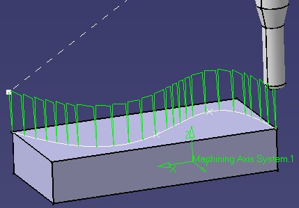
This use case computes a kind of "plunge roughing" tool path for CAASmgOperation.
| The tool path is created from the first guide of CAASmgGuide
and the CAAStep, CAAToolAngle and CAAApproachDistance parameters
|
|
[Top]
This use case is a part of Surface Machining Operation Sample [1]. You should build all the modules of this sample at a time to be able to launch it [2].
Don't forget to edit the interface dictionary located in:
| Windows | InstallRootDirectory\CAASurfaceMachiningItf.edu\CNext\code\dictionary\ |
| Unix | InstallRootDirectory/CAASurfaceMachiningItf.edu/CNext/code/dictionary/ |
where InstallRootDirectory is the directory where the CAA CD-ROM
is installed, and uncomment the appropriate lines by removing the '#' character.
[Top]
This use case is made of source files located in the CAASmiUserOperationToolPathReplay.m module of the CAASurfaceMachiningItf.edu framework:
| Windows | InstallRootDirectory\CAASurfaceMachiningItf.edu\CAASmiUserOperationpToolPathReplay.m |
| Unix | InstallRootDirectory/CAASurfaceMachiningItf.edu/CAASmiUserOperationpToolPathReplay.m |
where InstallRootDirectory is the directory where the CAA CD-ROM
is installed.
[Top]
CAASmiUserOperationWithUserMFToolPath is divided into the following steps
We now comment each of those sections by looking at the code.
[Top]
To customize the ComputeToolPath method, we should create an extension class that will implement CATIMfgComputeToolPathCustom:
... // Tie the implementation to its interface #include "TIE_CATIMfgComputeToolPathCustom.h" TIE_CATIMfgComputeToolPathCustom( CAAESmiUserOperationTPComputation); ... |
[Top]
To compute the tool path, we need the strategy and macros parameters of our operation. To retrieve them, we use the CATIMfgActivityParameters interface.
  ...
  // Reads Activity Parameters
  double Step = 0.;
  double ToolAngle = 0.;
  double ApproachDistance = 0.;
  CATIMfgActivityParameters * pActivityParameters = NULL;
  RC = QueryInterface(IID_CATIMfgActivityParameters, (void**) &pActivityParameters);
  if (SUCCEEDED(RC))
  {
    // Step
    pActivityParameters->GetValue ("CAAStep", Step);

    // ToolAngle
    pActivityParameters->GetValue ("CAAToolAngle", ToolAngle);

    // Approach distance
    pActivityParameters->GetValue ("CAAApproachDistance", ApproachDistance);

    pActivityParameters->Release();
    pActivityParameters = NULL;
  }
  ...
|
[Top]
To get geometry, we first retrieve the machining feature of our operation. Then, we use the GetGuides method of the specific CAAISmiUserMachFeature interface, described later, to find geometrical elements.
  ...
  // Retrieves Machining Feature from Activity
  CATBaseUnknown_var spBaseFeature = pActivity->GetFeature();

  // Retrieves Geometry from Machining Feature
  CATLISTP(CATGeometry) ListOfGeometry;
  CAAISmiUserMachFeature * pUserMachFeature = NULL;
  RC = spBaseFeature->QueryInterface(IID_CAAISmiUserMachFeature, (void**) &pUserMachFeature);
  if (SUCCEEDED(RC))
  {
    pUserMachFeature->GetGuides(ListOfGeometry);
    pUserMachFeature->Release();
    pUserMachFeature = NULL;
  }
  ...
|
A new interface CAAISmiUserMachFeature is implemented by CAAESmiUserMachFeature in CAASmiUserMachFeature.m module. This interface deals with the geometry attribute of CAASmgMachiningFeature.
In GetGuides, we retrieve the CAASmgGuide attribute from GetNcGeometryParameter of CATISmgNcGeometryManager and we get geometries from GetGeometricElements of CATISmgNcGeometryParameter.
  ...
  // Gets CAAGuide parameter
  CATBaseUnknown_var spParameter = NULL_var;
  RC = GetGuideParameter(spParameter);
  if (SUCCEEDED(RC))
  {
    CATISmgNcGeometryParameter * pSmgParameter = NULL;
    RC = spParameter->QueryInterface(IID_CATISmgNcGeometryParameter, (void**) &pSmgParameter);
    if (SUCCEEDED(RC))
    {
      pSmgParameter->GetGeometricElements(oGeometries);
      pSmgParameter->Release();
      pSmgParameter = NULL;
    }
  }
  return RC;
  ...
|
[Top]
The tool path is created and returned as a CATIMfgCompoundTraject smart pointer using the CreateMfgCompoundTraject of the CATIMfgToolPathFactory interface implemented by the Process document manufacturing container passed as input parameter. Then, a pointer to CATIMfgToolPathComponents is retrieved from the tool path and the tool path is initialized from the activity using the Init method of CATIMfgCompoundTraject.
The tool path data can now be created from parameters and geometry of the surface machining operation. Geometry tessellation is done by TessellateGeometry.
The CreateMfgTPMultipleMotion method of CATIMfgToolPathFactory creates the object which contains the motions. This object is added to the tool path thanks to the AddElement method of CATIMfgToolPathComponents.
With interface CATIMfgTPSaveData on tool path, the tool path is saved in the model with the method SaveData.
[Top]
This article provides an example on how to implement tool path computation of a new surface machining operation with a user machining feature.
It shows also how to get geometry from a new surface machining geometry attribute, illustrating the use of CATISmgNcGeometryParameter and CATISmgNcGeometryManager interfaces.
Now, let's have a look at the second scenario [4] of the Surface Machining Operation Sample.
[Top]
| [1] | Surface Machining Operation Sample Overview |
| [2] | Building and Launching a CAA V5 Use Case |
| [3] | Customizing Tool Path Computation on Axial Operation |
| [4] | Managing Geometry with Machining Areas |
| [Top] | |
| Version: 1 [Mar 2002] | Document created |
| [Top] | |
Copyright © 2002, Dassault Systèmes. All rights reserved.