Machining |
NC Review |
Customizing Tool Path Computation on Axial Operations (2)Implementing the CATIMfgComputeToolPathCustom interface |
| Use Case | ||
AbstractThis article discusses the CAAMaiToolPathWithCycleCustomization use case. |
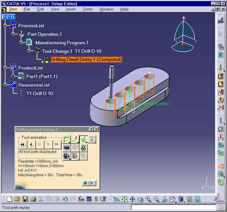
As CAAMaiToolPathCustomization [3] use case, this use case shows you how to create a tool path with the CATIMfgComputeToolPathCustom interface.
This use case shows how to create a machining cycle and to insert a "PP command" inside the tool path:
This use case focuses on tool path creation. To see more details about the use case, how to create and replay an operation, you should refer to the CAAMaiToolPathCustomization [3] use case.
[Top]
CAAMaiToolPathWithCycleCustomization is a use case of the CAAManufacturingItf.edu framework that illustrates ManufacturingInterfaces framework capabilities.
[Top]
Refer to CAAMaiToolPathCustomization [3] use case, to have more details about creation and replay of the operation.
You can also generate APT file.
With default options , the APT file is the following :
$$ Manufacturing Program.1
$$ Part Operation.1
$$*CATIA0
$$ Manufacturing Program.1
$$ 1.00000 0.00000 0.00000 0.00000
$$ 0.00000 1.00000 0.00000 0.00000
$$ 0.00000 0.00000 1.00000 0.00000
PARTNO PART TO BE MACHINED
COOLNT/ON
CUTCOM/OFF
PPRINT OPERATION NAME : Tool Change.1
$$ Start generation of : Tool Change.1
TLAXIS/ 0.000000, 0.000000, 1.000000
$$ TOOLCHANGEBEGINNING
RAPID
GOTO / 0.00000, 0.00000, 100.00000
CUTTER/ 10.000000, 0.000000, 5.000000, 2.886751, 30.000000,$
0.000000, 50.000000
TOOLNO/1, 10.000000
TPRINT/T1 Drill D 10
LOADTL/1
$$ End of generation of : Tool Change.1
PPRINT OPERATION NAME : Drilling Dwell Delay.1
$$ Start generation of : Drilling Dwell Delay.1
CYCLE/DRILL, 50.000000, 1.000000
GOTO / 100.00000, 0.00000, 50.00000
GOTO / 50.00000, 0.00000, 50.00000
GOTO / 0.00000, 0.00000, 50.00000
GOTO / -50.00000, 0.00000, 50.00000
GOTO / -100.00000, 0.00000, 50.00000
CYCLE/OFF
If you modify the "Output CYCLE Syntax" value
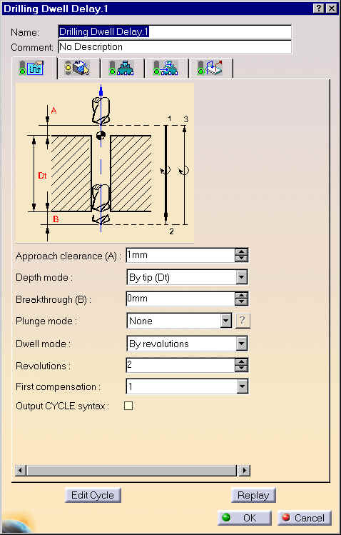
and generate the APT file again, you obtain:
$$ Manufacturing Program.1
$$ Part Operation.1
$$*CATIA0
$$ Manufacturing Program.1
$$ 1.00000 0.00000 0.00000 0.00000
$$ 0.00000 1.00000 0.00000 0.00000
$$ 0.00000 0.00000 1.00000 0.00000
PARTNO PART TO BE MACHINED
COOLNT/ON
CUTCOM/OFF
PPRINT OPERATION NAME : Tool Change.1
$$ Start generation of : Tool Change.1
TLAXIS/ 0.000000, 0.000000, 1.000000
$$ TOOLCHANGEBEGINNING
RAPID
GOTO / 0.00000, 0.00000, 100.00000
CUTTER/ 10.000000, 0.000000, 5.000000, 2.886751, 30.000000,$
0.000000, 50.000000
TOOLNO/1, 10.000000
TPRINT/T1 Drill D 10
LOADTL/1
$$ End of generation of : Tool Change.1
PPRINT OPERATION NAME : Drilling Dwell Delay.1
$$ Start generation of : Drilling Dwell Delay.1
LOADTL/1,1
FEDRAT/ 1000.0000,MMPM
SPINDL/ 70.0000,RPM,CLW
GOTO / 100.00000, 0.00000, 51.00000
GOTO / 100.00000, 0.00000, 0.00000
DELAY/ 2.000000,REV
GOTO / 100.00000, 0.00000, 51.00000
RAPID
GOTO / 50.00000, 0.00000, 51.00000
GOTO / 50.00000, 0.00000, 0.00000
DELAY/ 2.000000,REV
GOTO / 50.00000, 0.00000, 51.00000
RAPID
GOTO / 0.00000, 0.00000, 51.00000
GOTO / 0.00000, 0.00000, 0.00000
DELAY/ 2.000000,REV
GOTO / 0.00000, 0.00000, 51.00000
RAPID
GOTO / -50.00000, 0.00000, 51.00000
GOTO / -50.00000, 0.00000, 0.00000
DELAY/ 2.000000,REV
GOTO / -50.00000, 0.00000, 51.00000
RAPID
GOTO / -100.00000, 0.00000, 51.00000
GOTO / -100.00000, 0.00000, 0.00000
DELAY/ 2.000000,REV
GOTO / -100.00000, 0.00000, 51.00000
$$ End of generation of : Drilling Dwell Delay.1
SPINDL/OFF
REWIND/0
END
To launch CAAMaiToolPathWithCycleCustomization, you will need to:
| Windows | InstallRootDirectory\CAADoc\CAAManufacturingItf.edu\CNext\code\dictionary\ |
| Unix | InstallRootDirectory/CAADoc/CAAManufacturingItf.edu/CNext/code/dictionary/ |
where InstallRootDirectory is the directory where the CAA
CD-ROM is installed, and de-comment the following line by removing the '#'
character:
DrillingDwellDelay CATIMfgComputeToolPathCustom libCAAMaiToolPathWithCycleCustomization
| Windows | InstallRootDirectory\CAADoc\CAAManufacturingItf.edu\CNext\resources\graphic\ |
| Unix | InstallRootDirectory/CAADoc/CAAManufacturingItf.edu/CNext/resources/graphic/ |
The CAAMaiToolPathWithCycleCustomization use case is made of a class named CAAEMaiToolPathDrillingDwellDelayCustomization located in the CAAMaiToolPathWithCycleCustomization.m module of the CAAManufacturingItf.edu framework:
| Windows | InstallRootDirectory\CAADoc\CAAManufacturingItf.edu\CAAMaiToolPathWithCycleCustomization.m |
| Unix | InstallRootDirectory/CAADoc/CAAManufacturingItf.edu/CAAMaiToolPathWithCycleCustomization.m |
where InstallRootDirectory is the directory where the CAA CD-ROM
is installed.
[Top]
Only the creation of the tool path is detailed here.
Please refer to CAAMaiToolPathCustomization use case [3] to have more details about:
There are several steps in the tool path creation:
  // =======================================================================================
  // - Building The Tool Path
  // The structure of the tool path is as follows :
  //  Drilling Dwell Delay Operation --> CompoundTraject
  //                                                    --> MfgToolPathCycle
  //                                                             --> MultipleMotion
  //  "MfgToolPathCycle" models the "Drilling Dwell Delay" cycle
  //      --> storage of the NC_Command NC_DRILLING_DWELL_DELAY
  //      --> storage of the tool motions ("MultipleMotion")
  //  "MultipleMotion"
  //      --> For each hole
  //          * Rapid path from previous hole to current one
  //          * Downward machining path of the hole
  //          * Insertion of a NC_DELAY instruction
  //          * Upward machining path of the hole
  //
  // =======================================================================================


  CATIMfgToolPathFactory *piToolPathFactoryOnContainer = NULL;
  RC= spContainer->QueryInterface(IID_CATIMfgToolPathFactory,
	                             (void**) &piToolPathFactoryOnContainer);
  if (FAILED (RC)) return E_FAIL;

  //
  // Creation of tool path element
  //
  CATIMfgCompoundTraject_var spCompoundTraject =
	  piToolPathFactoryOnContainer->CreateMfgCompoundTraject();
  if (NULL_var == spCompoundTraject) return E_FAIL;
  CATIMfgToolPathComponents_var spToolPathComponentsOnCompound(spCompoundTraject);
  if (NULL_var == spToolPathComponentsOnCompound) return E_FAIL;
|
The tool path is created and returned as a CATIMfgCompoundTraject
smart pointer using the CreateMfgCompoundTraject method of the CATIMfgToolPathFactory
interface. This interface is implemented by the Process document
manufacturing container passed as input parameter.
The interface CATIMfgToolPathComponents (obtained from the CATIMfgCompoundTraject interface) allows you to add elements to the tool path.
// // Initialization of tool path from activity (copy of feedrates, spindle, ....) // spCompoundTraject->Init(spActivity); // // Initialization of tool axis on tool path // CATIMfgToolPathConstantToolAxis_var spToolAxis = piToolPathFactoryOnContainer ->CreateMfgToolPathConstantToolAxis(machiningToolAxis); if (NULL_var == spToolAxis) return E_FAIL; spCompoundTraject->SetToolAxis(spToolAxis); |
The method Init of the interface CATIMfgCompoundTraject
is used to initialize the tool path from the operation (feedrate values, spindle
speed value, tool or tool assembly, ...)
The tool axis is created thanks to the CreateMfgToolPathConstantToolAxis
method of CATIMfgToolPathFactory.This tool axis is set to the tool path
using the SetToolAxis method of CATIMfgCompoundTraject.
  //
  // Description of machining cycle
  //
  CATUnicodeString NC_Command ("NC_DRILLING_DWELL_DELAY");
  CATIMfgToolPathCycle_var ToolPathCycle =
	  piToolPathFactoryOnContainer->CreateMfgToolPathCycle(NC_Command);
  if (NULL_var == ToolPathCycle) return E_FAIL;
  spToolPathComponentsOnCompound->AddElement(ToolPathCycle);

  // Location points for the cycle description
  CATMathSetOfPoints LocationPoints;
  LocationPoints.SetNumberOfPoints (nbOfPts);
  for (int I = 1;I<=nbOfPts; I++)
  {
	  CATMathPoint LocationPoint = pointsInPattern.GetPoint(I-1);
	  LocationPoints.SetPoint (LocationPoint,I-1);
  }
  ToolPathCycle->SetCycleLocationPoints (LocationPoints);
|
The machining cycle (CATIMfgToolPathCycle interface) is created with
the method CreateMfgToolPathCycle of the CATIMfgToolPathFactory
interface. It is stored on the tool path with the AddElement
method.
The following data are stored on the object which implements the interface CATIMfgToolPathCycle:
  // Description of tool motions for the machining cycle
  CATIMfgToolPathComponents_var spToolPathComponentsOnCycle (ToolPathCycle);
  if (NULL_var == spToolPathComponentsOnCycle) return E_FAIL;
  CATIMfgTPMultipleMotion_var MultipleMotion =
	  piToolPathFactoryOnContainer->CreateMfgTPMultipleMotion();
  if (NULL_var == MultipleMotion) return E_FAIL;
  spToolPathComponentsOnCycle->AddElement(MultipleMotion);

  CATMathPoint previousClearPoint;
  for (I = 1; I<=nbOfPts; I++)
  {
	  CATMathPoint point = pointsInPattern.GetPoint(I-1);
	  CATMathPoint clearPoint = point + machiningToolAxis * clearTipValue;
	  CATMathPoint depthPoint = point - machiningToolAxis * depthValue;
	  CATListOfDouble X,Y,Z;
	  //
	  // Linking path in rapid feedrate between clearance points
	  //
	  if (I>1)
	  {
		  X.RemoveAll(); Y.RemoveAll(); Z.RemoveAll();
		  X.Append (previousClearPoint.GetX());
		  Y.Append (previousClearPoint.GetY());
		  Z.Append (previousClearPoint.GetZ());
		  X.Append (clearPoint.GetX());
		  Y.Append (clearPoint.GetY());
		  Z.Append (clearPoint.GetZ());
		  MultipleMotion->AddPolyline (TPLinkingTraject,TPRapidFeedrate,X,Y,Z);
	  }
	  //
	  // Downward machining path to machine the hole
	  //
	  X.RemoveAll(); Y.RemoveAll(); Z.RemoveAll();
	  X.Append (clearPoint.GetX());
	  Y.Append (clearPoint.GetY());
	  Z.Append (clearPoint.GetZ());
	  X.Append (depthPoint.GetX());
	  Y.Append (depthPoint.GetY());
	  Z.Append (depthPoint.GetZ());
	  MultipleMotion->AddPolyline (TPMachiningTraject,TPMachiningFeedrate,X,Y,Z);

	  //
	  // NC_DELAY Command
	  //
	  CATUnicodeString NCCommandName ("NC_DELAY");
	  MultipleMotion->AddPPCommand (NCCommandName);

	  //
	  //Downward machining path to machine the hole
	  //
	  X.RemoveAll(); Y.RemoveAll(); Z.RemoveAll();
	  X.Append (depthPoint.GetX());
	  Y.Append (depthPoint.GetY());
	  Z.Append (depthPoint.GetZ());
	  X.Append (clearPoint.GetX());
	  Y.Append (clearPoint.GetY());
	  Z.Append (clearPoint.GetZ());
	  MultipleMotion->AddPolyline (TPMachiningTraject,TPMachiningFeedrate,X,Y,Z);

	  previousClearPoint = clearPoint;
  }
|
The CATIMfgTPMultipleMotion object is created with the method CreateMfgTPMultipleMotion
of the CATIMfgToolPathFactory interface.
For each point of the pattern, this object contains successively:
TPLinkingTraject)
in rapid feedrate (TPRapidFeedrate) between the previous hole
to the current oneTPMachiningTraject) in machining
feedrate (TPMachiningFeedrate).TPMachiningTraject) in machining
feedrate (TPMachiningFeedrate).Note that the keywords such as TPMachiningFeedrate, TPMachiningTraject, ........ , used for tool path computation are located in the CATMfgToolPathDefs.h file.
// // Save tool path in model // CATIMfgTPSaveData_var spSaveData (spToolPathComponentsOnCompound); if (NULL_var == spSaveData) return E_FAIL; spSaveData->SaveData(); // // Return // spToolPath = spToolPathComponentsOnCompound; if (NULL_var == spToolPath) return E_FAIL; piToolPathFactoryOnContainer->Release(); piToolPathFactoryOnContainer = NULL; return RC; |
The tool path is saved in the model using the method SaveData of
its CATIMfgTPSaveData interface.
Then, the tool path is passed to the output parameter as a pointer to CATIMfgToolPath interface.
[Top]
This article provides an example on how to use the manufacturing interfaces, and has illustrated them on an axial tool path customization. It shows how to implement the CATIMfgComputeToolPath interface to compute the tool path of a "drilling dwell delay" operation in a process document that includes this operation as an activity. This document also includes the part to be machined, and the tool resources.
The use case focuses on the tool path creation and describes how to model a machining cycle inside a tool path : the object , which implements the interface CATIMfgToolPathCycle, contains the name of the cycle ("NC_DRILLING_DWELL_DELAY"), the location points to apply the cycle, and the related tool motions by using an object which implements the interface CATIMfgTPMultipleMotion.
The object which implements the CATIMfgTPMultipleMotion interface, contains the linear tool motions and a PP Command "NC_DELAY".
Depending on the attribute "Output CYCLE Syntax", the APT file contains:
CYCLE/DRILL, 50.000000, 1.000000
GOTO / ..............
..........
CYCLE/OFF
RAPID
GOTO / .......
GOTO / .......
DELAY/ 2.000000,REV
GOTO / .......
[Top]
| [1] | Building and Launching a CAA V5 Use Case |
| [2] | Process Modeler Home Page |
| [3] | CAAMaiToolPathCustomization use case |
| [Top] | |
| Version: 1 [Nov 2001] | Document created |
| [Top] | |
Copyright © 2001, Dassault Systèmes. All rights reserved.