Machining |
3 Axis Surface Machining |
Creating Surface Machining Operations OverviewA full example showing you how to add your own surface machining operations |
| Technical Article | ||
AbstractThis article discusses the CAASmiUserOperationCatalog, CAASmiUserOperationUI, CAASmiUserOperationWithMA, CAASmiUserOperationWithMAToolPath, CAASmiUserOperationWithUserMF and CAASmiUserOperationWithUserMFToolPath use cases. These use cases explain how to create and integrate new surface machining operations into CAA V5. |
These use cases are intended to help you make your first steps in creating new Surface Machining Operations.
The main intent is to explain:
These use cases include some knowledge from various V5 Frameworks, such as the Object Specs Modeler framework, or the Dialog and Dialog Engine Frameworks. Their intent is to focus on the use of the Surface Machining Infrastructure frameworks. A prerequisite knowledge of other Frameworks may be required to fully understand this use case, some links with other CAA use cases will help you navigate among them.
Notice that some of these use cases can be put into practice in others Manufacturing Frameworks, like Prismatic Machining.
Before getting to the tutorials, it is important to get an understanding of the use case scenarios. This is the goal of the next section.
Two scenarios are available:
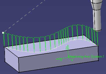
Scenario 1: Define a "Plunge" operation associated with a custom machining feature.
The goal of this scenario is to create a new operation CAASmgOperation. It has 3 parameters and it is connected with a new machining feature CAASmgMachiningFeature, linked to geometry by an attribute : CAASmgGuide. It computes a kind of "plunge roughing" tool path.
|
|
|
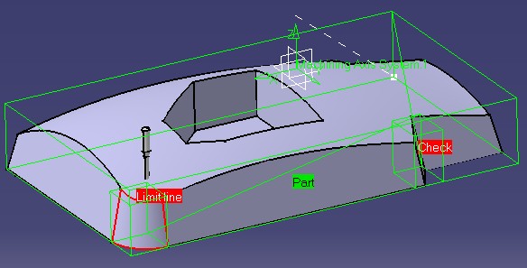
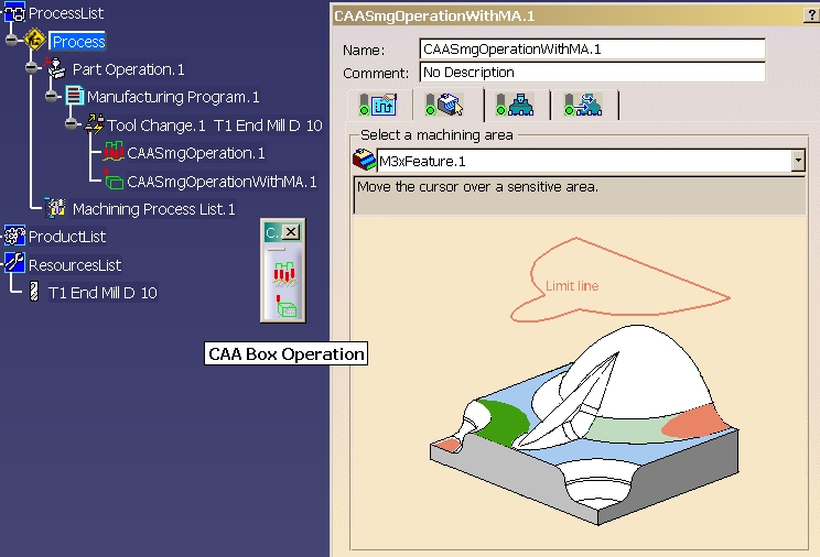
Scenario 2: Define a "Box" operation using machining areas.
The goal of this scenario is to create a second operation CAASmgOperationWithMA, illustrating the use of machining areas. It computes a tool path following the bounding boxes of the geometrical elements of a machining area.
|
|
|
This section will describe the different tasks to perform to achieve this sample.
The final intent of these use cases is to create some new surface machining operations. This is an end-to-end integration. At the end of this use case "Tour", you should hardly notice any difference between these operations and an original V5 surface machining operation.
The sample is divided into several steps. Following them leads to full defined surface machining operations:
To launch the use cases, you will need to set up the build time environment, then uncomment the lines of the interface dictionary, then compile all the modules of CAASurfaceMachiningItf.edu framework along with their prerequisites, and execute the use cases [3].
Be sure that use cases catalogs are stored in the CNext + resources + graphic directory of the runtime view. See CAASmiUserOperationCatalog use case.
|
When CATIA is opened,
|
 |
[Top]
The sample is made of a several modules of the CAASurfaceMachiningItf.edu framework:
| Windows | InstallRootDirectory\CAASurfaceMachiningItf.edu\ |
| Unix | InstallRootDirectory/CAASurfaceMachiningItf.edu/ |
where InstallRootDirectory is the directory where the CAA CD-ROM
is installed.
These modules are:
[Top]
The CAASurfaceMachiningItf.edu sample shows how to add new operations inside Surface Machining Infrastructure, using either an exisiting machining area, either a new user machining feature.
You can now successively go to:
[Top
| [1] | Creating an Add-in |
| [2] | Creating Features in an Applicative Container |
| [3] | Building and Launching a CAA V5 Use Case |
| [Top] | |
| Version: 1 [Mar 2002] | Document created |
| [Top] | |
Copyright © 2002, Dassault Systèmes. All rights reserved.