Machining |
3 Axis Surface Machining |
Computing a Tool Path with Machining AreasImplement CATIMfgComputeToolPathCustom on a surface machining operation using machining areas |
| Use Case | ||
AbstractThis article discusses the CAASmiUserOperationWithMAToolPath use case. It explains how to customize tool path computation of a surface machining operation with machining areas. This paper accompanies the second scenario of Surface Machining Operation Sample [1] and follows the CAASmiUserOperationWithMA use case. |
This use case is intended to help you to implement tool path computation of a surface machining operation.
More specifically, the CAASmiUserOperationWithMAToolPath Use Case shows how to:
Another use case describes in detail how to customize tool path computation [3].
[Top]
CAASmiUserOperationWithMAToolPath is a use case of the CAASurfaceMachiningItf.edu framework that illustrates Surface Machining capabilities. It is a part of the sample described in the technical article [1].
[Top]
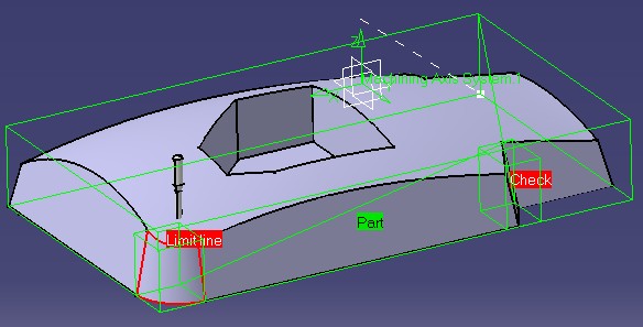
This use case computes the tool path of CAASmgOperationWithMA, connected with a machining area.
The tool path is created from the boundaries of geometrical elements of the connected machining area. The CAAOffset parameter can be used to inflate the boundaries on each direction.
[Top]
This use case is a part of Surface Machining Operation Sample [1]. You should build all the modules of this sample at a time to be able to launch it [2].
Don't forget to edit the interface dictionary located in:
| Windows | InstallRootDirectory\CAASurfaceMachiningItf.edu\CNext\code\dictionary\ |
| Unix | InstallRootDirectory/CAASurfaceMachiningItf.edu/CNext/code/dictionary/ |
where InstallRootDirectory is the directory where the CAA CD-ROM
is installed, and uncomment the appropriate lines by removing the '#' character.
[Top]
This use case is made of source files located in the CAASmiConnectUserOperationWithMA.m module of the CAASurfaceMachiningItf.edu framework:
| Windows | InstallRootDirectory\CAASurfaceMachiningItf.edu\CAASmiConnectUserOperationWithMA.m |
| Unix | InstallRootDirectory/CAASurfaceMachiningItf.edu/CAASmiConnectUserOperationWithMA.m |
where InstallRootDirectory is the directory where the CAA CD-ROM
is installed.
[Top]
CAASmiUserOperationWithMAToolPath is divided into the following steps:
We now comment each of those sections by looking at the code.
[Top]
To customize the ComputeToolPath method, we should create an extension class that will implement CATIMfgComputeToolPathCustom:
... // Tie the implementation to its interface #include "TIE_CATIMfgComputeToolPathCustom.h" TIE_CATIMfgComputeToolPathCustom( CAAESmiUserOperationWithMATPComputation); ... |
[Top]
To retrieve geometry of a machining area, we use the CATISmgMachiningAreaxxx interfaces:
  ...
  // Gets Machining Area
  CATBaseUnknown_var spBaseFeature = pActivity->GetFeature();
  if (!!spBaseFeature)
  {
    // Gets geometry from PART of the machining area
    CATISmgMachiningAreaParts * pParts = NULL;
    RC = spBaseFeature->QueryInterface(IID_CATISmgMachiningAreaParts, (void**) &pParts);
    if (SUCCEEDED(RC))
    {
      // Gets geometry of parts
      CATLISTP(CATGeometry) ListOfGeometries;
      RC = pParts->GetGeometricElements(ListOfGeometries);

      // Gets the bounding box of the geometry of the part body
      GetBoundingBox(ListOfGeometries,PartsBBox);

      pParts->Release();
      pParts = NULL;
    }

    // Gets geometry from CHECK of the machining area
    CATISmgMachiningAreaChecks * pChecks = NULL;
    RC = spBaseFeature->QueryInterface(IID_CATISmgMachiningAreaChecks, (void**) &pChecks);
    if (SUCCEEDED(RC))
    {
      // Gets geometry of checks
      CATLISTP(CATGeometry) ListOfGeometries;
      RC = pChecks->GetGeometricElements(ListOfGeometries);

      // Gets the bounding box of the geometry of the checks
      GetBoundingBox(ListOfGeometries,ChecksBBox);

      pChecks->Release();
      pChecks = NULL;
    }

    // Gets geometry from LIMITING CURVE of the machining area
    CATISmgMachiningAreaGuidingCurves * pGuidingCurves = NULL;
    RC = spBaseFeature->QueryInterface(IID_CATISmgMachiningAreaGuidingCurves, (void**) &pGuidingCurves);
    if (SUCCEEDED(RC))
    {
      // Gets geometry of Limiting Curves
      CATLISTP(CATCurve) ListOfCurves;
      RC = pGuidingCurves->GetResultingCATCurves(ListOfCurves);

      // Fill a list of CATGeometry from CATCurve
      CATLISTP(CATGeometry) ListOfGeometries;
      int NbCurves = ListOfCurves.Size();
      for (int ic=1;ic<=NbCurves;ic++)
      {
        ListOfGeometries.Append(ListOfCurves[ic]);
      }

      // Gets the bounding box of the geometry of the Limiting Curve
      GetBoundingBox(ListOfGeometries,GuidingCurvesBBox);

      pGuidingCurves->Release();
      pGuidingCurves = NULL;
    }
  }
 ...
|
[Top]
The tool path is created and returned as a CATIMfgCompoundTraject smart pointer using the CreateMfgCompoundTraject of the CATIMfgToolPathFactory interface implemented by the Process document manufacturing container passed as input parameter. Then, a pointer to CATIMfgToolPathComponents is retrieved from the tool path and the tool path is initialized from the activity using the Init method of CATIMfgCompoundTraject.
The tool path data is created from the boundaries of the machining area (computed with GetBoundingBox).
The CreateMfgTPMultipleMotion method of CATIMfgToolPathFactory creates the object which contains the motions. This object is added to the tool path thanks to the AddElement method of CATIMfgToolPathComponents.
With the interface CATIMfgTPSaveData on tool path, the tool path is saved in the model with the method SaveData.
[Top]
This article provides an example on how to implement tool path computation of a new surface machining operation with machining areas.
It shows also how to get geometry from a machining area, illustrating CATISmgMachiningAreaxxx interfaces.
[Top]
| [1] | Surface Machining Operation Sample Overview |
| [2] | Building and Launching a CAA V5 Use Case |
| [3] | Customizing Tool Path Computation on Axial Operation |
| [Top] | |
| Version: 1 [Mar 2002] | Document created |
| [Top] | |
Copyright © 2002, Dassault Systèmes. All rights reserved.