Machining |
3 Axis Surface Machining |
Managing Geometry with Machining AreasCustomize the geometry tab page of a surface machining operation with machining areas |
| Use Case | ||
AbstractThis article discusses the CAASmiUserOperationWithMA use case. It explains how to assign a surface machining operation to an existing machining area. This paper accompanies the second scenario of Surface Machining Operation Sample [1]. |
Machining areas are V5 SMG native features used to define different zones on a part.
This use case is intended to help you to manage geometry of a machining area assigned to a surface machining operation.
More specifically, the CAASmiUserOperationWithMA Use Case shows how to:
[Top]
CAASmiUserOperationWithMA is a use case of the CAASurfaceMachiningItf.edu framework that illustrates Surface Machining capabilities. It is a part of the sample described in the technical article [1].
[Top]
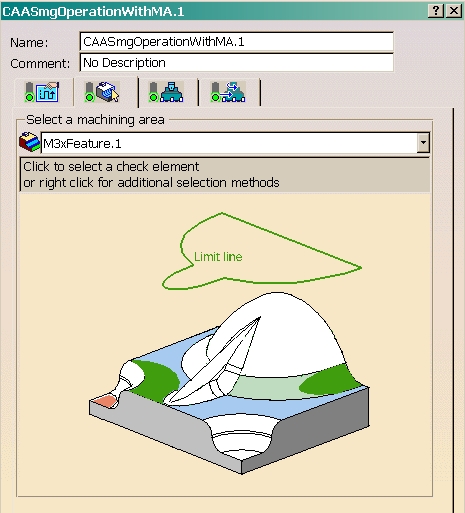
The goal of this use case is to define the geometry interactive of CAASmgOperationWithMA, using machining areas properties.
In the geometry tab page of CAASmgOperationWithMA, you can select a existing machining area and set its geometrical components (parts, checks, limit line and forbidden area):
[Top]
This use case is a part of Surface Machining Operation Sample [1]. You should build all the modules of this sample at a time to be able to launch it [2].
Don't forget to edit the interface dictionary located in:
| Windows | InstallRootDirectory\CAASurfaceMachiningItf.edu\CNext\code\dictionary\ |
| Unix | InstallRootDirectory/CAASurfaceMachiningItf.edu/CNext/code/dictionary/ |
where InstallRootDirectory is the directory where the CAA CD-ROM
is installed, and uncomment the appropriate lines by removing the '#' character.
[Top]
This use case is made of source files located in the CAASmiConnectUserOperationWithMA.m module of the CAASurfaceMachiningItf.edu framework:
| Windows | InstallRootDirectory\CAASurfaceMachiningItf.edu\CAASmiConnectUserOperationWithMA.m |
| Unix | InstallRootDirectory/CAASurfaceMachiningItf.edu/CAASmiConnectUserOperationWithMA.m |
where InstallRootDirectory is the directory where the CAA CD-ROM
is installed.
[Top]
CAASmiUserOperationWithMA is divided into the following steps:
We now comment each of those sections by looking at the code.
[Top]
To overload the geometry tab page, we should create an extension class that will implement CATIMfgGeometryActivity:
... // Tie the implementation to its interface #include "TIE_CATIMfgGeometryActivity.h" TIE_CATIMfgGeometryActivity( CAAESmiUserOperationWithMAGeometryEditor); ... |
In GetMainPanelEditor, we create a machining area (with CATISmgFactory) and associate it with CAASmgOperationWithMA. Then, we call the geometry dialog frame described below.
  ...
  if (!!spFeatCont)
  {
    CATISmgFactory * pSmgFactory = NULL;
    oRC = spFeatCont->QueryInterface(IID_CATISmgFactory, (void**) &pSmgFactory);
    if (SUCCEEDED(oRC))
    {
      // Creates a empty machining area
      oRC = pSmgFactory->CreateMachiningArea(spMachFeature);
      if (SUCCEEDED(oRC))
      {
        // Link the machining area to the activity
        pActivity->SetFeature(spMachFeature);
      }
      pSmgFactory->Release();
      pSmgFactory = NULL;
    }
    ...
  }

  // Creates the geometry frame
  oFrame = new CAASmiUserOperationWithMAGeometryPanel(iFather,this);
  ...
|
[Top]
CAASmiUserOperationWithMAGeometryPanel is the frame of the geometry tab page of CAASmgOperationWithMA.
In the constructor class, we build a dialog combo filled with all the machining areas in the model and we add a event notification sent whenever a value is selected in the combo list. Then, we get the default dialog frame of the selected machining area with the CATIEdit interface.
  ...
  // Creates a combo box
  _pDlgCombo = new CATDlgCombo(this,"DlgCombo",CATDlgCmbDropDown);
  if (_pDlgCombo)
  {
    ...
    // Fills the combo box
    if (!!spFeatCont)
    {
      // Finds all machining areas inside the model
      _pListOfMAs = spFeatCont->ListMembers("CATIM3xFeature");
      int NumbOfMAs = _pListOfMAs.Size();
      for (int i=1;i<=NumbOfMAs;i++)
      {
        CATUnicodeString Name;
        CATBaseUnknown_var spMachArea = _pListOfMAs[i];
        if (!!spMachArea)
        {
          CATIAlias * pAlias = NULL;
          HRESULT RC = spMachArea->QueryInterface(IID_CATIAlias, (void**) &pAlias);
          if (SUCCEEDED(RC))
          {
            Name = pAlias->GetAlias();
            _pDlgCombo->SetLine(Name);
            pAlias->Release();
            pAlias = NULL;
          }

          if (spMachArea->IsEqual(spCurrentMachArea) == 1)
            _pDlgCombo->SetSelect(i-1,0);
        }
      }
    }

    // Adds a callback
    AddAnalyseNotificationCB(
      _pDlgCombo,
      _pDlgCombo->GetComboSelectNotification(),
      (CATCommandMethod) &CAASmiUserOperationWithMAGeometryPanel::SelectMachArea,NULL);

    // Creates the Machining Area editor
    if (!!spCurrentMachArea)
    {
      CATIEdit * pEdit = NULL;
      RC = spCurrentMachArea->QueryInterface(IID_CATIEdit, (void**) &pEdit);
      if (SUCCEEDED(RC))
      {
        CATDlgFrame * pMAFrame = pEdit->GetPanelItem(this,"MAFrameID");
        if (pMAFrame)
          pMAFrame->SetGridConstraints( 1, 0, 2, 1, CATGRID_4SIDES);
        pEdit->Release();
        pEdit = NULL;
      }
    }
  ...
|
The SelectMachArea method is called whenever a new machining area is selected in the combo list. Here, the default dialog frame is updated with the CATIEdit interface:
  ...
  // Refresh Machining Area Editor
  CATIEdit * pEdit = NULL;
  RC = spMA->QueryInterface(IID_CATIEdit, (void**) &pEdit);
  if (SUCCEEDED(RC))
  {
    // As a frame called "MAFrameID" has already been created, the method GetPanelItem
    // will refresh it
    pEdit->GetPanelItem(this,"MAFrameID");
    pEdit->Release();
    pEdit = NULL;
  }
 ...
|
[Top]
This use case has demonstrated how to use machining areas with a surface machining operation.
We will see now how to compute the tool path of our operation [3].
[Top]
| [1] | Surface Machining Operation Sample Overview |
| [2] | Building and Launching a CAA V5 Use Case |
| [3] | Computing a Tool Path with Machining Areas |
| [Top] | |
| Version: 1 [Mar 2002] | Document created |
| [Top] | |
Copyright © 2002, Dassault Systèmes. All rights reserved.