
Mechanical Modeler |
The Contents of the Specification Container - Geometrical FeaturesWhat are the geometrical features? |
|
| Technical Article | ||
AbstractThe "Structure of the Part Document" article [1] shows that the Part document contains four main containers, one of which is the specification container. This container contains the mechanical features. The mechanical features can be divided in three categories:
This article is the last of a trilogy. Its aim is to detail the third category: what are the geometrical features, their type, the existing geometrical features, and how they are aggregated by geometrical features sets. The first article [2] details the Part feature: what is the Part feature, how is it created, how is it retrieved in a Part document ?. At last, the second article [3] details the geometrical features sets: their type, how are they created, how are they retrieved in a Part document. All these articles are included in a set of documents presented in the "Mechanical Modeler Overview" article. [4]. |
A geometrical feature is a mechanical feature to which the update mechanism, through the CATIBuild [5] interface, associates a topological result. This section presents an overview of these features thanks to the Mechanical StartUps tree and explains how a classification in relationship with the topology of the feature can be done.
The geometrical features derive from the GeometricalElement StartUp [6]. The picture [Fig.1] below is an extract of the mechanical StartUps tree:
|
There are some interfaces, implemented (*) on the GeometricalElement3D StartUp, which enables you to classify a geometrical feature by its topological result [5]. These interfaces are useful to filter selections, it means that you can use them in agent of selection for example.
The CATBody associated with the feature is a equivalent to a Point (CATPoint) , a Line (CATLine), a Plane (CATPlane) respectively.
All the domains (CATDomain) of the CATBody associated with the feature are infinite. (infinite line or plane)
All the domains (CATDomain) of the CATBody associated with the feature have the same dimension of 0,1, 2 or 3 respectively.
(*)The implementation is "conditional". It means that a QueryInterface
call on these interfaces will be successful only if the feature requires the
specificity of the interface. However, be aware that a feature may change of
type during its life.
A solid feature is a feature only referencing 3D geometry whereas a surfacic feature is a feature referencing 0D, 1D, 2D or 3D geometry.
In the general case, a feature deriving from the MechanicalShapeFeature StartUp is a solid feature and a feature deriving from the GSMGeom or GeometricalElement3D StartUps is a surfacic feature [Fig.1]. But there are at least two exceptions. The EdgeFillet feature, deriving from the MechanicalContextualFeature StartUp, can be locally a surfacic feature if it is aggregated in a GSMTool. Inversely, the Loft feature, deriving from the GSMGeom StartUp, can be locally a solid feature if it is aggregated in an HybridBody.
However, if this kind of behavior is possible for Dassault Systemes features, it is impossible for your features. A CAA geometrical feature deriving from MechanicalContextualFeature or MechanicalFormFeature is necessarily a solid feature, whereas a CAA feature deriving from GSMGeom or GeometricalElement3D is a surfacic feature [7].
The CATIMf3DBehavior interface enables you to know if a geometrical feature is solid or surfacic. These interface groups together methods which are exclusives:
IsASolid method returns S_OK,
and the other methods return E_FAIL,IsAShape method returns S_OK,
and the other methods return E_FAIL.For the volumes, the IsAShape method returns S_OK,
since a volume is a surfacic feature, but also the IsAVolume method
of the CATIMf3DBehavior2 interface.
A solid feature can be only included in a solid and surfacic features set, in other words a PartBody or a Body feature, as compared to a surfacic feature which can be included into any geometrical features set: a Geometrical Feature Set, an Ordered Geometrical Set, a PartBody, or a Body.
A solid feature can either be a form or a contextual feature.
A Pad, a Pocket, a Groove, are different features: some add matter, while some remove it. However, they share a common point: they have a Form and are therefore called Form features. What exactly are they ?
Take a Groove for instance. From its input parameters, a Curve and a closed Sketch, one can easily derive a shape (a Form) by sliding the Sketch along the Curve. The resulting solid has then to be operated with the Part's shape as it exists prior to the definition of the Groove, by removing matter (thanks to a boolean difference operation in this case).
The fact that these features can be applied by first computing their form and then operating the form with the current shape of the geometrical features set defines the form feature. The form of such a feature is sometimes called its footprint.
In contrast to Form features, Contextual features, cannot be applied by first computing a standalone footprint, and then operating it with the current set. Fillets, Drafts, and generally all Dress up features fall into this category, because their shape is determined not only by their own input parameters, but also by the local topology of the target set. Contextual features do not have a footprint.
The CATIShapeFeatureProperties (MechanicalModeler) enables the retrieval of the status of the solid feature.The first feature in a PartBody [3] cannot be a contextual feature because at this point there is no matter in the Part to operate upon. This constraint does not exist for the Body features. Since their ultimate goal is to be operated with the PartBody, the matter on which their first feature will operate will be provided by the PartBody. As a consequence, their first feature can be a contextual feature.
It must be noted that the fact that some features add and others remove matter from the Part is not linked to the form/contextual classification. A Draft is a contextual feature that adds matter, while a Chamfer, also contextual, removes it. A Revolution and a Pocket are form features that create and remove matter respectively.
Adding or removing matter defines the polarity of the solid feature. The CATIShapeFeatureProperties interface (MechanicalModeler) returns the polarity of the solid feature.
Note: The polarity of a Body/PartBody, which is the polarity of its first solid feature, is given by the same interface.
This distinction between a feature of creation and a feature of modification is meaningful for features inside an ordered set [8]. The interface specifying the classification is CATIInputDescription (InteractiveInterfaces).
A feature of creation is a feature creating matter from its input
specifications. For example, a line created from two points is a feature of
creation. A feature of modification is a feature modifying one or several
of its input specifications. For example, a split is a feature of modification.
The GetFeatureType method of the CATIInputDescription
enables you to specify the type of your feature. This type is not necessarily
fixed, it can be dependant of the values of inputs.
A feature of modification is also named an absorbent feature for the following behaviors on its modified inputs also named absorbed features:
 |
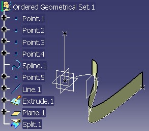 |
The right picture [Fig.2] shows the result of the split operation of Extrude.1
(a surface) by the plane Plane.1. Split.1 is the
feature representing the result. If you see the left picture [Fig.2]
which shows the
model before the split operation, you can note on the right that Extrude.1
is not drawn.
The absorbed features are returned by the GetListOfModifiedFeatures
method of CATIInputDescription. It can be one or several features, but
all are an input of the absorbent feature, and have the same
dimension as it.
One of these absorbed features is privileged. It is the feature returned by
the GetMainInput method. This feature has two roles:
 |
The color of Feat3, a feature of modification which has two inputs, is given by its main input, here it is Input2.
 |
If Feat4, a feature of modification, is moved before Feat3, the input of Feat4 becomes Input2 (the main input).
If your feature is a feature of creation, the GetListOfModifiedFeatures
and GetMainInput methods must return E_FAIL.
One of the major strengths of the Feature modeler [6] is that it allows the construction of a feature from other features. The result of one feature can be the inputs of another feature so that one can reach a linked flow of features characterizing the design intent. The modification of one of the parameters of one feature in the chain does not break the design since the update allows just the recalculation of the final result. We, therefore, have a record of the construction.
For some applications, this record is useless. So we have introduced the notion of a mechanical feature without history. This is the datum. A datum is a feature without input geometrical specifications.
A datum is not a specific feature: it is an existing feature with the
"datum" status. It can be, for example, a GSMPoint, a GSMLine, a
GSMPlane or a GeometricalElement3D feature. The CATIMf3DBehavior interface
and its IsaDatum method returns the status of the
feature.
(*) GSMPoint, GSMLine and GSMPlane are StartUps deriving from GSMGeom but not representing on the given UML schema [Fig.1].
Creating a datum can be done for other reasons:
The way to create a datum depends on the current application:
 |
The Line.1 feature has been created with the Point.1
and Point.2 features. But before executing the Line command, the ![]() CreateDatum setting has been activated. Next, the
CreateDatum setting has been activated. Next, the Point.1 has
been moved, but the line has not changed. (Points are represented by white
crosses, and the line ends by two black dots).
 |
The PartBody has been selected, and with the contextual menu,
the Copy/Paste Special command with the "Paste As Result" option has
been executed. The Solid.1 feature has been created.
Note: If the "Paste As Special With Link" is chosen, this means that a link to the original feature has been kept. A modification in the feature modifies the datum after an update.
There are three ways to code the creation of a datum:
This interface enables the transformation of an existing feature to a feature without specifications. But this interface is only available for few features: Point, Line, Plane, Circle.
A feature is created using a CATBody. Based on this topological object, a surface, a plane, a point, a solid feature is created.
There are two available methods:
InstantiateDatum(CATBody* iBody,CATISpecObject* &oDatumFeature)This method creates the scope [10] with an automatic naming.
InstantiateDatum(CATBody* iBody,CATLISTP(CATCell)* iGNUserCells,CATListOfCATUnicodeString* iUserKeys,CATISpecObject* &oDatumFeature)This method enables driving yourself the naming of the following cells. The "Creating a Result Without Procedural Report" chapter of the article entitled "Integrating the New Mechanical Feature in the Update Mechanism" [5] gives the details to fill these lists.
The created features are the following:
Caution: With the second InstantiateDatum method, with the
list of cells and the list of keys, a GeometricalElement3D is created instead
a basic feature (Point, Line, Plane, Circle).
In certain cases, the topology is not fixed, it must be generated at each update. In this case, you should create a new geometrical feature which will derive from the GeometricalElement3D [Fig.1] StartUp. The "Creating a New StartUp Deriving from a Mechanical StartUp" article [7] gives all the steps to create it. This feature must necessarily implement the following interfaces:
Refer to the "Creating a Result Without Procedural Report" section of the "Integrating the New Geometrical Feature in the Update Mechanism" article [5]
The new feature is a surfacic feature and a datum feature:
For the other behaviors, refer to the article entitled "Integrating a New Mechanical Feature in V5" [11].
Dassault Systemes provides Mechanical features through applications such as Part Design or Generative Shape Design. This section lists them, as well as the related interfaces that manage them.
They are not represented on the GeometricalElement Architecture UML Schema [Fig.1], most of them derive from the Solid feature.
These features derive from the GSMGeom feature. [Fig.1]. You can create them with the CATIGSMFactory (GSMInterfaces) interface:
The geometrical features sets are the PartBody feature, the Body features, the Ordered Geometrical Set features, and the Geometrical Set features [3].
Before going further, let us review the vocabulary
This insertion is depending on three things:
The features created by the CATIGSMFactory interface (The Generative Shape Design Features section) are to be aggregated after their creation, whereas the features created by the CATIPrtFactory/CATIPrtBooleanFactory interfaces (The Part Design Features section) are automatically included in the current set.
Consequently, for features created by the CATIGSMFactory interface, and for your CAA features (surfacic or not), read the How to aggregate a geometrical feature into a geometrical features set section for explanations about the aggregation.
To aggregate a solid feature, the used interface is not the same as for a surfacic feature. The methodology is explained in the How to aggregate a geometrical feature into a geometrical features set section.
Whatever the factory, and whatever the type of the feature, if the set is
ordered, the aggregation is not sufficient. After the aggregation and after the
update of the feature, you must invoke the Insert method of the CATMmrLinearBodyServices
class. This method manages the re-root of the features into the ordered set.
[8].
To aggregate a solid feature inside a PartBody or a Body, the InsertInProceduralView
method of the CATIPrtProceduralView interface must necessarily be used. Refer to the "A
Chain of Features"
section of the "Specification/Result Mechanism Applied to Mechanical Feature" article
[8].
For any surfacic feature you can use the CATIDescendant
interface. But, if the surfacic feature derives from GSMGeom, it is
recommended to use the InsertInProceduralView
method of the CATIGSMProceduralView.
If the set is ordered, the new feature must be located just after the current feature, if
the current feature is into the set, otherwise located at the end of the
set. The both InsertInProceduralView
methods manage the right location. If you use the CATIDescendant, here
it is a piece of code to manage the good location:
...
int pos = 0 ;
CATISpecObject_var CurrentElt = GetCurrentFeature() ;
if ( NULL_var != CurrentElt)
{
   pos = pIDescendantsOnGSMTool->GetPosition(CurrentElt);
}

if ( 0 == pos )
{
   pIDescendantsOnGSMTool->Append(piSpecOnCombinedCurve);
}else
{

   pIDescendantsOnGSMTool->AddChild(piSpecOnCombinedCurve,pos+1);
}
...
|
It is an extract of the combined curve use case [12] where:
GetCurrentFeature is a method of the command where is extract
this codepIDescendantsOnGSMTool, is a CATIDescendant interface pointer
on the setpiSpecOnCombinedCurve is a CATISpecObject interface
pointer on the feature to aggregatepos
is zero. The new combined curve is aggregated at the end of the set thanks
to the Append method.pos is
not nul. The new combined curve is aggregated just after the current feature
thanks to the Addchild method.There is another advantage to use the CATIGSMProceduralView instead of the CATIDescendants interface for a surfacic feature. The first interface creates a Geometrical Set, if the current set is not a surfacic set. It is possible if the PartBody or the Body features have been instantiated from the MechanicalTool StartUp. It means that your Part document was created before the R14.
[Top]
The specification container is one of the containers of the Part document. It groups together the mechanical features. Among these are the geometrical features which hold a topological result. There are two kinds of geometrical features:
In most cases, this is the feature deriving from the MechanicalShapeFeature StartUp. It is aggregated either by the PartBody, or a Body. Both are solid and surfacic features sets. There are the form features having a footprint and the contextual features which need an initial form to be computed with it.
In most cases, this is the feature deriving either from the GSMGeom StartUp or the GeometricalElement3D StartUp. It is aggregated either by Ordered Geometrical Set, or a Geometrical Set. Both are surfacic features sets.
A solid feature or a surfacic feature can be a datum. A datum is a feature without specifications, it contains only the result, a CATBody.
To insert a geometrical feature into a set:
Insert method
of the CATMmrLinearBodyService if the set is ordered.[Top]
| Version: 1 [Dec 2002] | Document created |
| Version: 2 [Jun 2003] | Document updated to specify the feature's classification |
| Version: 3 [Nov 2003] | Document updated for OGS integration |
| Version: 4 [Nov 2003] | Document updated for R14 novelties |
| [Top] | |
Copyright © 2002, Dassault Systèmes. All rights reserved.