Mechanical Modeler |
Generic Naming OverviewAccessing sub-elements |
|
| Technical Article | ||
AbstractThis article gives a short description of the Generic Naming mechanism used in V5. Having a hands-on experience of the Modeler Feature [1] and the Topologic Modeler [2] is necessary to take full benefits from this article. |
In V5, a feature cannot reference directly a topology as a specification [1]. The main raison is that geometry and topology can be deleted and replaced during an update. In fact topological objects are unstable.
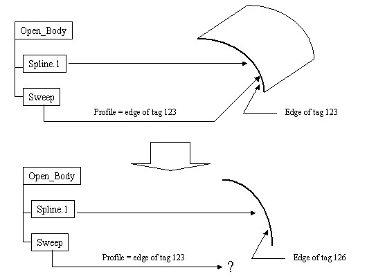
Consider the following example. The use has created a sweep that uses the resulting edge of a spline feature as a profile. Suppose now, that the sweep references the edge directly using its geometrical tag. Whenever the user modifies the spline, the topology is deleted and replaced by a new one that may have a different tag.
The tag used by the sweep is now referencing an element that no longer exists. The sweep cannot be recalculated.
|
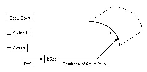
The solution implemented in V5 to overcome this problem is to use a name instead of a direct reference to the topology. In our example [Fig.1], instead of pointing directly to the edge, the sweep will store a name that describe precisely this cell, for instance "result edge of the feature Spline.1". Even after an update the sweep will be able to find the correct topology in the result by interpreting the name.
Such a name is called a generic name or a stable name. It provides a stable way to reference a topological cell. Generic names are managed by the Generic Naming layer of the V5.
Generic names can be made persistent and stored in some specific features, called BRep features. BRep features are always hidden to the end-user. They are aggregated by other features and are used as input specifications. The interface to manage these features is CATIMfBRep (MechanicalModeler).
 |
[Top]
When a user selects interactively a topological cell, CATIA automatically calculates a generic name for this cell and stores it in a temporary object. This object is an object of selection (not a feature) managed by the CATIBRepAccess interface (MecModInterfaces). This object of selection is a temporary handler on the cell. From an object of selection it is possible to access the feature that own the cells or the cell itself.
CATIA calculates the generic naming by reading a kind of history graph of the topological objects. This graph describes the construction relations that exist between the cells of several bodies.
The graph used by the generic naming is generated during the update process. The purpose of this graph is to help the application to build generic names for selected elements. This graph is made of scopes and nodes.
To each mechanical feature is associated with only one scope. The scope makes the link between the feature and its topological result (a CATBody). A scope contains one or several nodes. Each node is linked to a cell of the result CATBody.
A node can also reference a node of a different scope is there is a construction relationship between the two cells. Nodes that do not have ancestor relationship can have a complementary info that helps in identifying the node.
In the example below, we show a simplified view of the graph generated by a Sketch and a Pad. In this figure [Fig.3], the node (n1) which is linked to the side face of the Pad (the one in gray) references the node (n2) which is linked to the Line.1of the Sketch. This relationship expresses the fact that the face has been generated from the line.
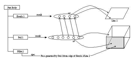 |
In this example, the generic name of the grayed face will be: Face generated by Pad.1, from the edge of Sketch.1/Line.1.
We can see that every side face of the Pad will have a different name. However, it is not possible to distinguish the top and the bottom face of the Pad. Both are built using the same elements. In that case it is necessary to add some information to the nodes of the top and bottom faces.
For a Pad, the top face will have the complementary information Top and the bottom face will have the info Bottom.
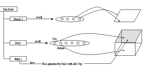 |
This added info will be used to build the generic name. In our example the name of the top face will be: Face generated by Pad.1 with info Top.
Not all the cells of a CATBody needs to be tracked by the nodes of a graph. In the above example, we can see that each edge is shared by only two faces. Therefore it is possible to identify an edge by saying that it is the common edge between two given faces.
Therefore, the generic naming graph will no keep track of every topological cells. It will only follow:
The graph is generated during the update process of the Part document. Each
mechanical feature is responsible for the generation of its own scope and nodes.
This is generally done in the Build method of the CATIBuild
interface [3].
To be used as a specification, the object of selection that contains the generic name must be transformed in a persistent object called a BRep feature. This process is called the featurization. It is the topic of the next paragraph.
An object of selection is a temporary object that is returned when the user selects or pre-selects a geometry. A BRep feature is a persistent object that stores the name of a topological cell. This name can be used later on to retrieve the cell. Only a BRep feature can be referenced as an input specification by another feature.
A CATPathElement (Visualization) can return BRep object. It will never return a BRep feature. The CATIFeaturize interface can be used to create a BRep feature from an object of selection.
It is also possible to use a CATFeatureImportAgent (DialogEngine) instead of CATPathElementAgent (DialogEngine) to generate automatically a BRep feature from a selected cell.
Several options are available when performing a featurization either manually using CATIFeaturize or automatically using a CATFeatureImportAgent . These options are:
This option will determine which feature (or scope) will be used to solve the BRep name and find the pointed cell.
This option will determine is the BRep feature should have its one scope.
This option should not be set. The default value should always be used.
Here an example to illustrate the options:
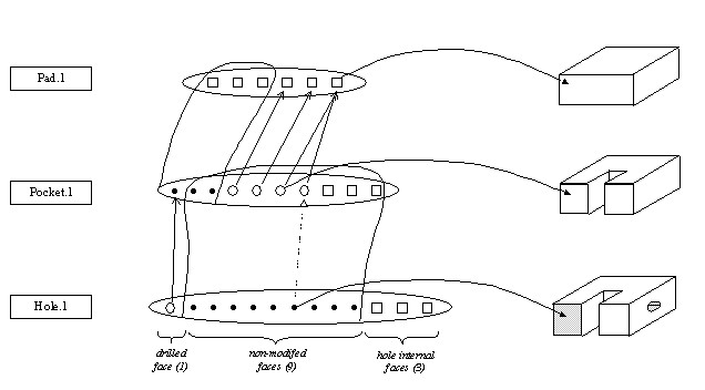 |
Suppose that the user has selected the face in gray, in the result body of the Hole (Hole.1). Now let's consider the creation of a BRep feature from this selected cell.
The first option will determine if the BRep should point specifically on the relimited geometry of if is should point on the functional, in that case both faces will not be distinguish.
The second option (support type) will determine which feature is used to search for the cell
Usually BRep will be created using one of the two sets of options:
[Top]
| [1] | Feature Modeler Overview |
| [2] | Topological Modeler |
| [3] | Integrating a New Geometrical Feature in the Update Mechanism |
| [Top] | |
| Version: 1 [Dec 2002] | Document created |
| [Top] | |
Copyright © 2002, Dassault Systèmes. All rights reserved.