
Mechanical Modeler |
The Structure of a Part DocumentDescription of the Part's containers |
|
| Technical Article | ||
AbstractLike any V5 document, a Part document contains a certain number of containers. This article describes them and explains their functionalities. This article is included in a set of documents presented in the "Mechanical Modeler Overview" article [1]. |
Like any V5 document, a Part document contains a certain number of containers. The containers specific to a Part document are shown in the picture below [Fig.1]:
|
The four containers: the product container (CATProdCont), the specification container (CATPrtCont), the scope container (CATMFBRP) and the geometrical container (CGMGeom) are strongly linked and work together as will be described in the last section. But first, here is a description of their contents and functionalities.
Any Part document has a Product container named CATProdCont. It contains an
ASMProduct feature which serves as the reference for all the instantiations of the Part
document in Product documents. In the picture below [Fig.2],
Part1.1 is an instance of the ASMProduct feature contained in
a Part document.
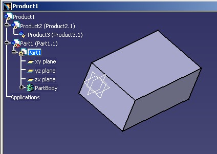 |
The Product instance (here Part1.1) contains the position of the Part inside the Product
document. The Product
Structure use case entitled "Positioning Products in a Product Document" [2] explains how to retrieve and
define the position of a sub-product.
The ASMProduct feature, retrievable by the CATIPrtPart interface (MecModInterfaces), also enables the creation of publications. Refer to the CATIPrdObjectPublisher interface of the Product Structure framework for more details.
The components of a Product document are ASMProduct feature handling by the CATIProduct
interface. Consider below, ispProduct, a such element. The GetReferenceProduct
method retrieves the reference feature contained in the CATProdCont
container of the Part document. Thanks this feature, the CATILinkableObject
interface gives you the Part document containing this feature.
  ...
  CATIProduct_var spRef = ispProduct->GetReferenceProduct();

  if ( NULL_var != spRef )
  {
     CATILinkableObject * piLinkableObject = NULL;
     rc = spRef->QueryInterface( IID_CATILinkableObject, (void**)& piLinkableObject );

     if ( SUCCEEDED(rc) )
     {
        // Do not release the document pointer
        CATDocument * pDocument = NULL ;
        pDocument = piLinkableObject->GetDocument();
...
|
The CATIContainerOfDocument (MecModInterfaces) implemented on the Part document enables the retrieval of a pointer to the product container.
  ...
  CATDocument * pDocument = ...
  CATIContainerOfDocument * pIContainerOfDocumentOnDoc = NULL ;
  HRESULT rc = pDocument->QueryInterface(IID_CATIContainerOfDocument,
                              (void**)&pIContainerOfDocumentOnDoc)
  if (SUCCEEDED(rc) )
  {
      CATIContainer * pIContainer = NULL ;
      rc = pIContainerOfDocumentOnDoc->GetProductContainer(pIContainer);

  }
  ...
|
The specification container, named CATPrtCont, contains the design of the mechanical object. This design is defined by mechanical features which can be seen in the specification tree [Fig.3]:
 |
Part1, xy plane, yz plane, zx plane, PartBody, Sketch and Pad.2 are mechanical features. There are three kinds of mechanical features:
The "Contents of the Specification Container" articles details the Part feature [4], the geometrical features sets [5], and the geometrical features [6].
There are three ways to retrieve this container:
  ...
  CATDocument * pDocument = ...
  CATIContainerOfDocument * pIContainerOfDocumentOnDoc = NULL ;
  HRESULT rc = pDocument->QueryInterface(IID_CATIContainerOfDocument,
                              (void**)&pIContainerOfDocumentOnDoc)
  if (SUCCEEDED(rc) )
  {
      CATIContainer * pIContainer = NULL ;
      rc = pIContainerOfDocumentOnDoc->GetSpecContainer(pIContainer);

  }
  ...
|
  ...
  CATInit * pInitOnDoc = NULL ;
  HRESULT rc = pDocument->QueryInterface(IID_CATInit, (void**)&pInitOnDoc ) ;
  if ( SUCCEEDED(rc) )
  {
     CATIPrtContainer *pIPrtCont = NULL ;
     pIPrtCont = (CATIPrtContainer*)
                    pInitOnDoc->GetRootContainer("CATIPrtContainer");
  }
  ...
|
In the case of a Part document, the root container is CATPrtCont.
  ...
  CATISpecObject * pSpecObjectOnFeat = NULL ;
  HRESULT rc = pMyFeat->QueryInterface(IID_CATISpecObject, (void**)&pSpecObjectOnFeat ) ;
  if ( SUCCEEDED(rc) )
  {
     CATIContainer_var spISpecCont = pSpecObjectOnFeat->GetFeatContainer();
  }
  ...
|
where pMyFeat is a pointer on any feature. spISpecCont
is a handle on the CATPrtCont container.
During the design, it can be useful to select an edge, or a face, for example, to create a form. These topological objects will be the inputs of a mechanical feature. But a feature cannot reference directly a topology as specification. The main reason is that geometry and topology can be deleted during an update. Consequently topological objects are unstable. The solution implemented in V5 to overcome this problem is to use a name instead of a direct reference to the topology. Such a name is called a generic name [7]. It provides a stable way to reference a topological cell.
The Scope container contains the objects, or scopes, used by Generic Naming.
The CATIContainerOfDocument (MecModInterfaces) implemented on the Part document enables the retrieval of a pointer to the scope container.
  ...
  CATDocument * pDocument = ...
  CATIContainerOfDocument * pIContainerOfDocumentOnDoc = NULL ;
  HRESULT rc = pDocument->QueryInterface(IID_CATIContainerOfDocument,
                              (void**)&pIContainerOfDocumentOnDoc)
  if (SUCCEEDED(rc) )
  {
      CATIContainer * pIContainer = NULL ;
      rc = pIContainerOfDocumentOnDoc->GetBRepContainer(pIContainer);

  }
  ...
|
Mechanical features essentially capture the design intent of the end user. When it comes to computing the shapes that correspond to this intent, they rely on an underlying modeler, the topological objects modeler. [8]
The geometrical container contains the topological results of the geometrical features. Refer to the "Specification/Result Mechanism Applied to Mechanical Features" [9] article for details on this topic.
The CATIContainerOfDocument (MecModInterfaces) implemented on the Part document enables the retrieval of a pointer to the geometrical container.
  ...
  CATDocument * pDocument = ...
  CATIContainerOfDocument * pIContainerOfDocumentOnDoc = NULL ;
  HRESULT rc = pDocument->QueryInterface(IID_CATIContainerOfDocument,
                              (void**)&pIContainerOfDocumentOnDoc)
  if (SUCCEEDED(rc) )
  {
      CATIContainer * pIContainer = NULL ;
      rc = pIContainerOfDocumentOnDoc->GetResultContainer(pIContainer);

  }
  ...
|
pIContainerOfDocumentOnDoc implements for example
the CATIGeoFactory interface.
[Top]
All the mechanical features are included in the specification container. Among the mechanical features, one can find the geometrical features. A geometrical feature has the particularity of having a result which holds a topological result. The topological result, a CATBody, is included in the geometrical container. The scope which guaranties the naming stability of the sub-elements of the CATBody is contained in the scope container.
 |
[Top]
The Part document contains four main containers:
The Product container which contains the reference to enable the instantiation of the Part in Product documents
The Specification container which contains the mechanical features
The scope container which contains the objects necessary to access the sub-elements of the topology
The geometrical container which contains the topological results of the mechanical features.
[Top]
| Version: 1 [Dec 2002] | Document created |
| Version: 2 [May 2004] | Document updated |
| [Top] | |
Copyright © 2002, Dassault Systèmes. All rights reserved.