Mechanical Modeler |
Integrating a New Geometrical Feature in the Update MechanismImplementing the CATIBuild and CATIBuildShape interfaces on geometrical features |
|
| Technical Article | ||
AbstractThe aim of this article is to explain the implementation of the CATIBuild interface on the geometrical feature [1]. This interface is used in the Update mechanism to build the result of the features. The article is divided in three parts:
To take full advantage of this advanced article, a pre-requisite knowledge of the Feature Modeler [2] and the Mechanical Modeler [3] is essential. |
This interface is called whenever an object need to be updated. Consequently, the feature will get an associative geometric result computed by objects coming from the Geometric Modeler's frameworks.
This interface has only one method, the Build method, whose the contents depends on the geometrical feature, but whose the main purpose is always the same:
|
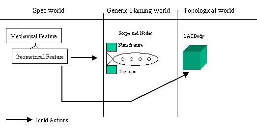
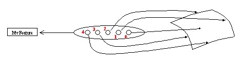
In this above figure [Fig.1] you should notice two things:
Build method generates a CATBody and a scope with
nodes,While the CATBody is created by topological operators, the scope creation is dependant on the geometrical feature type:
The feature has no history, so its scope will also be without history. This means that the nodes of such scopes are not linked to nodes of other scopes. The "Creating the Result without Using a Procedural Report" section details this case.
To build the geometry of such feature, the geometry of its geometrical input specifications is necessary. However, in the same way that the geometry is based on the re-use of the cells, the scope creation will re-use the nodes of the scopes of the input specifications.
This operation, creating the scope, falls within the competence of the Procedural
Report that need to be created at the beginning of the Build
method and saved at the end. The "Creating
the Result Using a Procedural Report" section presents the generic
code. The "Geometrical Feature Specificity"
section details the implementation for the three possible geometrical
features: a surfacic feature, a contextual feature and a form feature. The
last two being solid features. See the article entitled "The Contents of
the Specification Container - Geometrical Features" [1] which
explains these three types of geometrical features.
A knowledge of the topology in general [5] [6], and the topological report [7] in particular is strongly recommended.
Once the implementation of the CATIBuild interface has been accomplished, a verification of the result is necessary. The CATMmrVerifyUpdate application enables you to check the validity of the new feature. The article entitled "Verifying the Validity of a Geometrical Feature" [8] explains how to use this application.
Note : All algorithms used to generate geometries are
versioned. Indeed, several internal algorithms exist to compute topological
results.
Consequently, in the two cases (Creating a Datum or using a Feature with
geometrical specifications) a Software Configuration has to be retrieved
on the feature to choose the right algorithm before generating results. This
configuration has to be stored on the instance at the end of the build method to
keep this information. [14]
[Top]
We are in the case of a datum, a feature without any geometrical specification. The "Datum versus Specification" section of the article entitled "The Contents of the Specification Container - Geometrical Features" [1] gives more details about this kind of geometrical feature.
In this case, you have to compute a Geometrical result (a CATBody).
And, after this computing, the scope will be generated "from scratch" using
good API.
However, as CGM algorithms are versioned, you have to retrieve the Algorithm
Configuration associated to your feature before computing its geometrical
result. This is done thanks to
CATMmrAlgoConfigServices services. [14]
  ...
  CATSoftwareConfiguration * pSoftConfig = NULL;
  rc = CATMmrAlgoConfigServices::GetConfiguration(pSOCombinedCurve ,pSoftConfig ,IsConfigToStore);
  if(SUCCEEDED(rc))
  {
    CATTopData TopData ;
    TopData.SetSoftwareConfiguration(pSoftConfig);
  ...
|
Then, with this TopData, you can generate the geometry associated to your feature, using the good algorithm level...
... CATTheTopoOperator * pTopoOperator = NULL ; pTopoOperator = ::TopologicalGlobalFunction(pIGeomFactory,pTopData,...); CATBody * pBody = pTopoOperator -> GetBodyResult(); ... |
At the end of the build method, the Software configuration, mandatory to generate geometrical result, would be stored if it is needed. This is done with CATMmrAlgoConfigServices::StoreConfiguration method.
  ...
  if(IsConfigToStore == 1)
  {
    CATMmrAlgoConfigServices::StoreConfiguration(pSOFeature, pSoftConfig);
  }
  ...
|
where
IsConfigToStore is the value retrieved by
CATMmrAlgoConfigServices::GetConfiguration pSOFeature is a CATISpecObject's pointer on the current
featurepSoftConfig is the Algorithm Configuration to store.Now, as the geometry is created, you just have to create the scope associated.
To create this scope, you must use the CreateScopeResult
method of the CATIMfResultManagement interface. This method allows you to
generate a scope that does not contain a history. This means that the nodes of
such scopes are not linked to nodes of other scopes.
As we have seen in the "Generic Naming" [4]
document, the name of a cell is computed using the historical relationship that
exists between the nodes and using the specific information added to the node.
For a node generated with CreateScopeResult only the added
information is available. As a matter of fact, a generic name cell will always
looks like:
Cell of dimension X generated by feature Y with info Z |
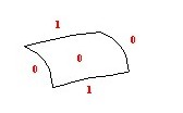
This means that for a given feature, the cells with the same information will have exactly the same generic name. The end user will not be able to select them individually.
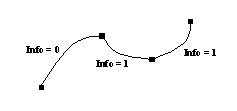 |
In this example, the end user will be able to select either the edge with information 0 or the two edges with information 1 together. He will not be able to select one of the two edges with information 1 individually.
The CreateScopeResult method has two signatures. The simple
signature takes only the CATBody as input parameter. It will generate a
scope that contains one node for each cell that must be followed. Each node will
have a different info. Therefore each cell will be selectable.
 |
In this example the CreateScopeResult method has generated
the nodes and has associated to each node a different information value. Each
cell will be selectable individually, and can be used as a specification by
another mechanical feature.
...
CATBody * pBody = operator->GetBodyResult() ;
CATIMfResultManagement* pIMfResultManagement =NULL ;
HRESULT rc = QueryInterface(IID_CATIMfResultManagement,
(void**)&pIMfResultManagement );
if ( SUCCEEDED(rc) )
{
rc = pIMfResultManagement->
|
where pBody is a CATBody created previously
by using the appropriate topological operators.
However if the feature is updatable, then there is no guarantee that the information that must be associated with each cell will be the same after the update. In other words, this feature is not associative, since the way its cells are named is not stable. To overcome this problem, it is possible to use a more complex signature that allows an application to specify the information that must be associated with each of the following cells of the CATBody. These following cells are:
If this signature is used, then it is the responsibility of the application to ensure that the naming will be consistent. Being consistent implies that:
The same information will not used to name cells of different dimension - [Fig.4]
After an update, an information will not switch to a cell of a different dimension - [Fig.5]
 |
This naming is not consistent because two cells of different dimension have the same info 0. |
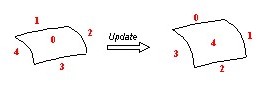 |
This naming is not consistent after the update because:
|
This complex signature can be used to limit the user's possibility in terms of selectable cells. For example, a feature might generate a complex geometry made of multiple faces. By using the same information for every face, it is possible to prohibit the selection of the individual faces. This may be necessary if the application cannot guarantee the number of faces or if it is meaningless to use only one face to build the next geometry.
Example:
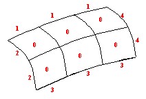 |
In this example, the user will be able to select:
He will not be able to select each face individually or the internal edges of the shell. The application can safely change the number of faces in the result. |
The code is the following:
...
CATBody * pBody = operator->GetBodyResult() ;
CATLISTP(CATCell)ListOfFollowedCells = ... ;
CATListOfCATUnicodeString ListOfUserKey = ... ;
CATIMfResultManagement* pIMfResultManagement =NULL ;
HRESULT rc = QueryInterface(IID_CATIMfResultManagement,
(void**)&pIMfResultManagement );
if ( SUCCEEDED(rc) )
{
rc = pIMfResultManagement ->
|
Where:
pBody is a CATBody created previously by using the
appropriate topological operators.ListOfFollowedCells is the list of the selected following
cells. ListOfUserKey is the list of keys. Each key must be a
number. Note: ListOfFollowedCells and ListOfUserKey are two
lists with the same size.
[Top]
We are in the case of a feature having geometrical specifications. The procedural report allows the application to benefit from a more complex algorithm for node creation. It also allows the creation of nodes that are linked to other nodes through historical relationships. The following schema explains the creation of the scope by using a Procedural report.
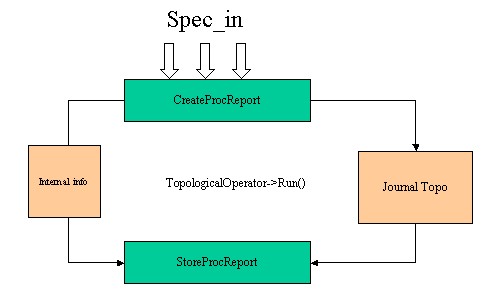 |
There are three main steps to create the result:
It is in
the third step that the Mechanical Modeler will create the scopes and the nodes
of the feature according to its topological result. It will also establish
relations between new nodes and nodes of the input scopes according to the
topological journal.
Usually,
the topological journal is generated by the topological operator during the
calculating of the result. CAA based operators may have to manage their own
journal.
You should use the CreateProcReport method of the CATIMfProcReport
interface (MechanicalModeler) implemented on the geometrical feature.
  ...
  CATLISTV(CATBaseUnknown_var) ListSpec ;
  CATListofCATUnicodeString ListKey ;
  int BoolOper = 0 ; // or 1
  ...
  CATIMfProcReport *pIMfProcReportOnThis =NULL ;
  HRESULT rc = QueryInterface(IID_CATIMfProcReport,
                                                 (void**)&pIMfProcReportOnThis );
  if ( SUCCEEDED(rc) )
  {
     rc = pIMfProcReportOnThis->CreateProcReport(ListSpec,ListKey,BoolOper);
  ...
|
where:
ListSpec is the list of specificationsThe list of specifications must contain the mechanical features whose scopes are needed to build the new scope.
ListKey is a list of keysThe list of keys must have the same number of elements than the list of specifications. The default value is
MfKeyNone. A different key value will indicate that the historical relationship of a node should be replaced with a user information. The value of the key must be in relationship with the information given by the topological report.Example:
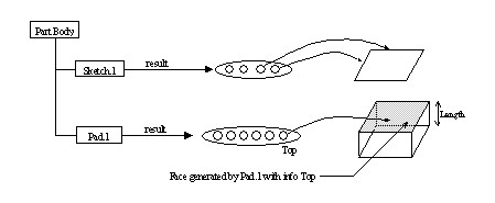
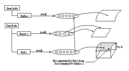
Consider the case of a pad. The top face of a pad can be computed by extruding the sketch to a numerical length [Fig. 8] or it can be calculated up to a given surface [Fig. 9]. In the first case, the top face will have the Top information. In the second case, the top face will have a historical relationship with the limiting face. As a matter of fact the naming will be different and switching between the two options will break any other feature which is using the top face as an input specification.
Fig.8:
Fig.9: The solution to this problem is to use a keyword
MfKeyTopfor the limiting surface to tell V5 that the historical relationship between the top face and the limiting surface must be replaced by a Top information. Then the name of the top face will be the same as for a pad with a given length
BoolOper is an integer value
The integer value indicates which feature will own the generated scope:
Build
method or Form feature in BuildShape
method )Build method )CreateProcReport method use the
default value, NULL_varThe topological operators need an object which contains:
GetCGMJournalList
method,
  ...
  CATCGMJournalList *pCGMJournalList = NULL ;
  pCGMJournalList = pIMfProcReportOnThis->GetCGMJournalList() ;
  ...
  CATSoftwareConfiguration * pSoftConfig = NULL;
  rc = CATMmrAlgoConfigServices::GetConfiguration(pSOCombinedCurve ,pSoftConfig ,IsConfigToStore);
  if(SUCCEEDED(rc))
  {
    pTopData = new CATTopData(pSoftConfig,pCGMJournalList );
  ...
|
One or several topological operators can be used to create the final result.
... CATTheTopoOperator * pTopoOperator1 = NULL ; pTopoOperator1 = ::TopologicalGlobalFunction(pIGeomFactory,pTopData,...); pTopoOperator1 ->Run(); CATBody * pBody1 = pIMfProcReportOnThis->GetResult(); ... CATTheTopoOperator * pTopoOperator2 = NULL ; pTopoOperator2 = ::TopologicalGlobalFunction(pIGeomFactory,pTopData,...); pTopoOperator2 ->Run(); ... CATBody * pResultBody = pIMfProcReportOnThis->GetResult(); ... |
Where TopologicalGlobalFunction is a simulated topological
operator. The first argument of an operator is always the geometrical factory
interface. This interface is implemented on CGMGeom, the
geometrical container of the Part document. Refer to the article entitled
"The Structure of the Part Document" [9] to
retrieve it.
The geometrical result is returned by the method GetResult
of the CATIMfProcReport interface pointer on the current feature. The
result of the Build method is the result computed after the last
operator. The intermediate results must be deleted from the geometrical
factory:
... pIGeomFactory->Remove(pBody1); ... |
To close the procedural report, use the StoreProcReport method
on the CATIMfProcReport interface pointer on the current feature.
... pIMfProcReportOnThis->StoreProcReport(pResultBody, TypeProcReport, BoolOper) ... |
where
pResultBody is the CATBody computed by the topological
operator - See the Running the
Topological Operator(s) sectionTypeProcReport, has two possible values:The copy/no copy convention used by the procedural report for an input should be the same as the one used internally by the topological operator for this input.
BoolOper: should have the same value as the one specified in
the CreateProcReport method - see Creating
the Procedural Report
On the First Build call, the feature determines its AlgorithmConfiguration.
This data has to be stored to insure versionning of this feature [14]
To store it, use the StoreConfiguration method
of the CATMmrAlgoConfigServices.
  ...
  if(IsConfigToStore == 1)
  {
    CATMmrAlgoConfigServices::StoreConfiguration(pSOFeature, pSoftConfig);
  }
  ...
|
where
IsConfigToStore is the value retrieved by
CATMmrAlgoConfigServices::GetConfiguration pSOFeature is a CATISpecObject's pointer on the current
featurepSoftConfig is the Algorithm Configuration to store.
In the previous section, the generic contents of the Build
method for a feature with geometrical specifications has been explained. The aim
of the current one is to detail the only three possible cases: the surfacic
feature, the contextual feature and the form feature. For each one, the
parameters for the procedural report and the possible operators are
presented.
Reading the "Specification/Result Mechanism Applied to Mechanical Features" [10] is recommended to take full advantage of this chapter.
We are in the case where the feature derives either from the GSMGeom or from the GeometricalElement3D StartUp.
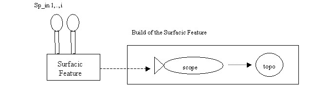 |
In most cases, the features to follow by the procedural report are all the sp_in features. See the Combined Curve use case for a complete example. [11]
This is the case where the feature derives from the MechanicalContextualFeature StartUp.
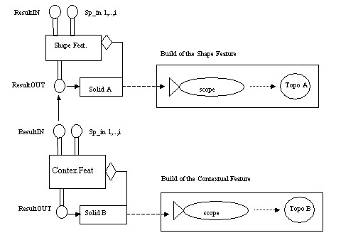 |
To create the geometry, Topo B, associated with the feature
result, Solid B, of the Contextual feature, a topological operation
will be executed on the geometry (Topo A) pointed by the Solid
A feature
The list of features to insert in the procedural report are:
Solid A) - Use
the GetBodyINAttributes method of the CATIShapeFeatureBody
(MechanicalModeler) interface to retrieve the ResultIN attribute. (The
ResultIN feature must exist otherwise it is an error)For the topological operator, you can for example use the CATDynFillet operator created by the CATCreateDynFillet global function.
... CATDynFillet * pDynFillet = NULL ; pDynFillet = ::CATCreateDynFillet(pIGeomFactory,iTopData,spResultInBody); ... |
where spResultInBody is the CATBody (Topo A)
associated with the ResultIN feature . Use the GetBodyIN
method of the CATIShapeFeatureBody (MechanicalModeler) interface to
retrieve it. The other parameters of the topological operator are explained in
the "Running the Topological
Operator(s)" section.
Topo B will be the resulting geometry retrieved by the GetResult
method of the CATIMfProcReport. See the "Running
the Topological Operator(s)" section.
This is the case where the feature derives from the MechanicalFormFeature StartUp.
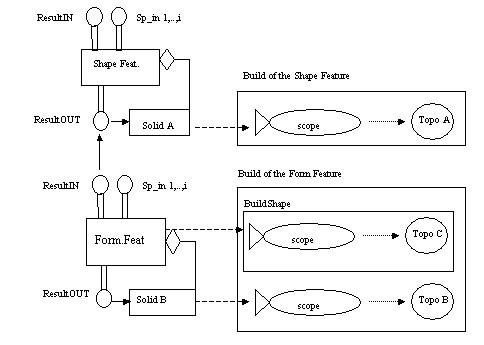 |
To create the geometry, Topo B, associated to the result
feature, Solid B, of the form feature, there are two steps
Topo C. This is
done by the CATIBuildShape interface implemented by the Form
feature.Topo C and the
geometry associated to the feature Solid A (Topo A)The topological body (Topo C) and the scope associated with the
form feature are created by the BuildShape method of the CATIBuildShape
(MecModInterfaces) interface. This method has the same architecture as the Build
method. See the next chapter entitled "Architecture
of the Build and BuildShape Methods".
You can use a topological operator such as CATDynBoolean created by the CATCreateDynBoolean global function.
...
  CATDynBoolean * pDynBoolean = NULL ;
  CATDynBooleanType = CATBoolUnion ; // or CATBoolIntersection or CATBoolRemoval
  pDynBoolean = ::CATCreateDynBoolean(pIGeomFactory,iTopData,CATDynBooleanType,
                                               spResultInBody,spFormBody);
 ...
|
where:
spResultInBody is the CATBody (Topo A)
associed to the ResultIN feature. Use the GetBodyIN method of
the CATIShapeFeatureBody (MechanicalModeler) interface to retrieve
it.spFormBody is the CATBody associated to the form
feature (Topo C). Use the GetShape method of the CATIShapeFeatureBody
(MechanicalModeler) interface to retrieve it.Topo B is the resulting geometry returned by the GetResult
method of the CATIMfProcReport. See "Running
the Topological Operator(s)"
The Part Design use case "Implementing a Mechanical Design Feature Building" presents an example for a form feature.
[Top]
The purpose of these two methods is always the same:
A CATMfErrUpdate instance class will be created. It will be
associated with the feature thanks to the CATIUpdateError interface.
The Build or the BuildShape methods return the
error by a CATThrow . [12]
For more information about the CATTry/CATCatch/CATThrow mechanism,
refer to the "Managing Errors Using Exceptions" article [13]
The Build method returns S_OK and the BuildShape method
returns 0 .
The CATIMechanicalProperties interface enables you to
de-activate/re-activate a feature from the update mechanism. In the solid features case (MechanicalFormFeature and MechanicalContextualFeature) this flag
is automatically taken into account, meaning that the CATIBuild interface
is not called in the feature update. But for a surfacic feature (GSMGeom
and GeometricalElement3D) the CATIBuild interface is always called. So,
you have to manage the activation flag inside the Build method
except for features deriving from GeometricalElement3D: the CATIMechanicalProperties interface
is not available for this feature.
The structure of the Build and the BuildShape
methods are the following:
HRESULT MyClass::Build()
{
   HRESULT rc = S_OK ;

   Declaring Useful Pointers

   CATTry
   {
      Testing the feature de-activation
      ...
      if ( feature active )
      {
         if ( feature is a form feature )
         {
            int value = BuildShape();
            if ( 0 != value )
               rc = E_FAIL;
         }
         if ( SUCCEEDED(rc) )
         {
            Cleaning Last Error

            Creating the Feature Result (scope and topology)

            Cleaning Useless Data
         }
      }
   }

   CATCatch(CATMfErrUpdate,pMfErrUpdate)
   {
      Processing a CATMfErrUpdate Error
   }
   CATCatch(CATError,pError)
   {
      Processing a CATError Error
   }

   CATEndTry

   return rc ;
}
|
Before the CATTry section you declare all the pointers:
CATTry and CATCatch sections: such
as piUpdateErrorOnThis the CATIUpdateError interface
pointer on the feature.
CATTry section and not released before the
call of a method which can throw an error All these pointers will be deleted/removed/released in the CATCatch
sections if an error occurs, see the "Deleting
the Useless Pointers" section. Otherwise, the same pointers will be
cleaned during the CATTry section and at the last of this section,
see the "Cleaning Useless Data"
section.
The first thing to do in the Build method is to check whether
the feature is active or not. Note that in the BuildShape method
this is not necessary because for a form feature, the Build and the
BuildShape methods are not called.
...
      CATIMechanicalProperties * pIMechanicalProperties = NULL;
      rc = QueryInterface(IID_CATIMechanicalProperties,pIMechanicalProperties );

      if ( SUCCEEDED(rc) && ( 1 == pIMechanicalProperties->IsInactivate())
      {
         QueryInterface(IID_CATIMfProcReport,(void **)& _pIMfProcReport);
         rc = pIMfProcReport->InactivateResult();
      }
...
|
The CATIMechanicalProperties interface enables you to know the status
of the feature. The InactivateResult method of the CATIMfProcReport
processes the result de-activation. _pIMfProcReport is a
CATIMfProcReport interface pointer declared before the CATTry section,
because the InactivateResult
method can throw an error.
If you have used the CATIMfResultManagement to create a result without a procedural report, you should not have to test the feature de-activation, because your feature being a datum must not implement the CATIMechanicalProperties interface.
This first step consists in invalidating the error which has perhaps been associated with the feature at the previous update.
  ...
  CATIUpdateError *pIUpdateErrorOnThis =NULL ;
  HRESULT rc = QueryInterface(IID_CATIUpdateError ,
                                        (void**)&pIUpdateErrorOnThis );
  if ( SUCCEEDED(rc) )
  {
     rc = pIUpdateErrorOnThis ->UnsetUpdateError();
  ...
|
This part is explained in the "Creating the Result without Using a Procedural Report" and "Creating the Result Using a Procedural Report" sections.
Releasing or deleting the useless objects created for the result.
In most cases, the current error is sufficient and it can be associated with the feature without modification.
  ...
  CATCatch(CATMfErrUpdate,pMfErrUpdate)
  {
     pIUpdateErrorOnThis ->SetUpdateError(pMfErrUpdate);

     Deleting the Result

     Deleting the Useless Pointers

     CATRethrow;
  }
...
|
pIUpdateErrorOnThis is a CATIUpdateError interface
pointer on this
The SetUpdateError method does several things:
Deleting the Result: You have only to delete the scope, you should never remove, from the geometrical container, the result CATBody. This object is managed by the scope.
...
p
|
Where pIMfResultManagement is a CATIMfResultManagement
interface pointer on this.
...
p
|
Where pIMfProcReportOnThis is a CATIMfProcReport
interface pointer on this.
Deleting the Useless Pointers:
Deleting/Removing/Releasing the pointers declared before the CATTry
sections- see the Declaring Useful
Pointers section- used in the CATTry sections and not
released before a method which can throw an error.
In certain cases, you have to create a new CATMfErrUpdate class instance.
  ...
  CATCatch(CATMfErrUpdate,pMfErrUpdate)
  {
       CATMfErrUpdate *pNewMfErrUpdate = new CATMfErrUpdate();

       ::Flush(pMfErrUpdate);

       pIUpdateErrorOnThis ->SetUpdateError(pNewMfErrUpdate);

       pNewMfErrUpdate->SetDiagnostic("MyOwnMessage");

       Deleting the Result

       Deleting the Useless Pointers

       CATThrow(pNewMfErrUpdate);

  }
...
|
pIUpdateErrorOnThis is a CATIUpdateError interface
pointer on this
Flush global function enables you to properly clean the
error
Some is the CATError class, you should return a CATMfErrUpdate class instance to prevent the update mechanism from displaying the "Update Diagnosis" dialog box.
  ...
  CATCatch(CATError,pError)
  {
     ::Flush(pError);

     CATMfErrUpdate *pNewMfErrUpdate = new CATMfErrUpdate();

     pIUpdateErrorOnThis ->SetUpdateError(pNewMfErrUpdate);

     pNewMfErrUpdate->SetDiagnostic("MyOwnMessage");

     Deleting the Result

     Deleting the Useless Pointers

     rc = E_FAIL ;
  }
...
|
[Top]
The CATIBuild interface enables you to generate the result of the feature. In the case of a geometrical feature, this result consists in:
The new feature is without geometrical input specifications. It is a datum.
The new feature has geometrical input specifications. The scope will be created thanks to a procedural report.
Please, note that topological result and scope are linked to a defined Algorithm Configuration which determine versioning of feature.[14]
[Top]
| Version: 1 [Dec 2002] | Document created |
| Version: 2 [Jan 2007] | Document updated with Algorithm Configuration |
| [Top] | |
Copyright © 2002, Dassault Systèmes. All rights reserved.