Geometric Modeler |
Topology |
Using the Topological ObjectsCreation of and navigation in a tetrahedron |
| Use Case | ||
AbstractThe goal of this use case is to understand the topological model of the CATIA geometric modeler, by creating a tetrahedron only with the TopologicalObjects resources. Topological objects can also be directly created by topological operators, and the use of topological operators is the recommended way rather than using the basic tools of the TopologicalObjects framework. The navigation in a topological structure is also discussed. |
The topological model is fully described in technical articles [1] [2]. The use case shows how to use the TopologicalObjects interfaces to create and explore topological objects.
[Top]
The intent of this section is to recall some important notions about the topological model.
The topology manages the Boundary Representation of an object: what it bounds and how.
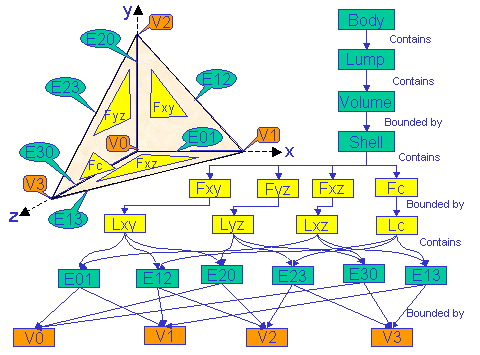
A cell is the lowest level of topological objects. There are four types of cells:
Connected cells of same dimension are grouped into domains to define the boundary of another cell. We can now detail the above definitions:
The body is the highest level of topological object: it is a set of lumps, shells, wires, and vertices in volume. The topological operators operate on bodies,... and it is often much more simpler to use a topological operator than to create the topology from scratch!
[Top]
CAATobTetra is a use case of the CAATopologicalObjects.edu framework that illustrates TopologicalObjects framework capabilities.
[Top]
The use case details the creation of the geometry and of the topology of the tetrahedron. Moreover, it scans the created topology.
|
The tetrahedron is a volume bounded by a shell containing 4 faces. Each face is bounded by a loop containing 3 edges, and two adjacent faces have a common edge: the edge makes the connection between the faces. Hence, there are 6 edges in the whole body. In the same way, edges are bounded (and connected) by vertices: there are four vertices. |
The topology bounds the geometry. Hence, the geometry of a vertex is a point, the geometry of a curve and the geometry of a face is a surface. In the CATIA geometric model, any kind of CATSurface can be the geometry of a CATFace. But the geometry of a CATEdge can only be a special type of curve called CATEdgeCurve, and the geometry of a CATVertex can only be a special type of point called CATMacroPoint.
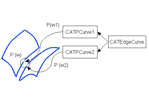 |
The CATEdgeCurve is the geometric representation of a curve,
that internally has several facets. In the case of Fig. 2, the
CATEdgeCurve represents the geometry of the intersection between two
surfaces, that is to say the CATPCurves lying on the two surfaces.
The CATPCurve is able to map a parameter (P(w1)) on one curve to its equivalent on the other curve (P(w2)): the evaluation of P(w1) on CATPCurve1 and the evaluation of P(w2) on CATPCurve2 give the same 3D location. |
The description of the geometry and of the cells is not sufficient to describe the topology: there is still to define the inside and outside of the objects. Several orientation properties must be set, that will be described when needed in the use case:
[Top]
To launch CAATobTetra, you will need to set up the build time environment, then compile CAATobTetra.m along with its prerequisites, set up the run time environment, and then execute the use case [5].
If you simply type CAATobTetra with no argument, the use case executes, but doesn't save the result in an NCGM file. If you want to save this result, provide the full pathname of the NCGM file to create. For example:
With Windows CAATobTetra e:\TetraCreation.NCGM
With UNIX CAATobTetra /u/TetraCreation.NCGM
This NCGM file can be displayed using the CAAGemBrowser use case.
[Top]
The CAATobTetra use case is made of a main named CAATobTetra.cpp located in the CAATobTetra.m module of the CAATopologicalObjects.edu framework:
| Windows | InstallRootDirectory\CAATopologicalObjects.edu\CAATobTetra.m\ |
| Unix | InstallRootDirectory/CAATopologicalObjects.edu/CAATobTetra.m/ |
where InstallRootDirectory is the directory where the CAA CD-ROM
is installed.
[Top]
The use case is divided into the following steps:
[Top]
The geometry factory (CATGeoFactory) creates and manages all the CATICGMObject (and the curves and surfaces in particular) [4]. This creation is done by the global function ::CATCreateCGMContainer. Notice that the factory can be defined by reading a NCGM file that was previously stored. In that case, the global function ::CATLoadCGMContainer must be used.
CATGeoFactory* piGeomFactory = ::CATCreateCGMContainer() ; if (NULL==piGeomFactory) return (1); |
[Top]
The topology is a logical information describing the boundary of geometric objects: so, first create the geometry!
To create planes, directly use the CreatePlane method of the CATGeoFactory. If NULL pointers are returned, close the factory and return an error.
  CATPlane * piPlanexy = piGeomFactory->CreatePlane(CATMathPoint(),
                                                    CATMathPoint(1,0,0),
                                                    CATMathPoint(0,1,0));
  CATPlane * piPlaneyz = piGeomFactory->CreatePlane(CATMathPoint(),
                                                    CATMathPoint(0,1,0),
                                                    CATMathPoint(0,0,1));
  CATPlane * piPlanexz = piGeomFactory->CreatePlane(CATMathPoint(),
                                                    CATMathPoint(1,0,0),
                                                    CATMathPoint(0,0,1));
  CATPlane * piPlanec  = piGeomFactory->CreatePlane(CATMathPoint(10,0,0),
                                                    CATMathPoint(0,10,0),
                                                    CATMathPoint(0,0,10));
  // is all right?
  if (NULL==piPlanexy || NULL==piPlaneyz || NULL==piPlanexz || NULL==piPlanec)
  {
    ::CATCloseCGMContainer(piGeomFactory);
    return (1);
  }
|
Now, create CATPLine on the planes. A CATPLine is a
line defined in the parameter space of a surface: it is natively on the surface.
To define it, two parameters are needed: the parameters of the start and end
limits of the line. But the parameterization of the CGM surfaces is not public:
the way to map a parameter into a 3D point is not published. The ways to define
a CATSurParameter are:
CAAGobCreation
use case [6].The following code creates the CATPLine.
The CATPCurve must be used to create the real geometry of the edge: the CATEdgeCurve. In the use case case, as the geometry are planes, we know that the two CATPCurve of an edge curve have no gap: we can directly create the edge curve using the CreateSimCurve method of the CATGeoFactory. Another way is to use the geometric intersection operator CATIntersectionSurSur, that can output the intersection of two surface as an edge curve.
 |
EC01 is the edge curve that is the geometry of edge
E01. It represents PLxy01 on the plane Pxy and PLxz01
on the plane Pxz. These two CATPCurve have the same orientation
(1 value) as the orientation of their edge curve.
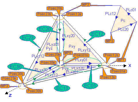
The edge is bounded by two vertices whose geometry are the macro point MP0 and MP1. These macro points are created by concatenation of points on the edge curves (CATPointOnEdgeCurve or Poec): for example MP1 represents Poec13s (start of edge curve EC13), Poec01e (end of edge curve EC01) and Poec12s (start of edge curve EC12 ). EC20 is the edge curve that is the geometry of edge E20. It represents PLxy20 on the plane Pxy and PLyz01 on the plane Pyz. PLxy20 has the same orientation as the orientation of its edge curve whereas PLyz01 has the opposite orientation (-1 value). |
Before defining the CATMacroPoint, just create the points on the edge curves. These points on edge curve define the geometry of the start and end of each edge curve. As there are 4 edge curves, 8 points on edge curves are needed (see Fig. 3). To compute a point on edge curve, the use case proposes to retrieve the current limits of the curve. Another way is to use a CATIntersectionCrvCrv operator. The CreatePointOnEdgeCurve method of the CATGeoFactory creates the poec, by using a curve of the edge curve. Notice that you can retrieve the corresponding parameter on the other curves of the edge curve by the GetEquivalentParam method of the CATEdgeCurve.
Appending the points on the edge curves in the corresponding macro points, and the geometry is completed.
[Top]
Before creating any topological entity, you first must create the factory of these entity: this factory is a CATBody, and not the CATGeoFactory. The factory of the CATBody, however, still is the CATGeoFactory.
  // ----------- Creates the factory of the cells
  //
  CATBody * piTetra = piGeomFactory->CreateBody();
  // is all right?
  if (NULL==piTetra)
  {
	::CATCloseCGMContainer(piGeomFactory);
	return (1);
  }
|
Using Tetra as the cell factory, we can now create the vertices, and associate them with their geometry (macro point).
  CATVertex *piVertex0=NULL, *piVertex1=NULL, *piVertex2=NULL, *piVertex3=NULL;
  piVertex0 = piTetra->CreateVertex();
  piVertex1 = piTetra->CreateVertex();
  piVertex2 = piTetra->CreateVertex();
  piVertex3 = piTetra->CreateVertex();
  // is all right?
  if (NULL==piVertex0 || NULL==piVertex1 ||NULL==piVertex2 ||NULL==piVertex3)
  {
	::CATCloseCGMContainer(piGeomFactory);
	return (1);
  }
  // Associates with their geometry
  piVertex0->SetPoint(piMacro0);
  piVertex1->SetPoint(piMacro1);
  piVertex2->SetPoint(piMacro2);
  piVertex3->SetPoint(piMacro3);
|
[Top]
First create them void.
  CATEdge *piEdge01=NULL, *piEdge12=NULL, *piEdge20=NULL,
	      *piEdge23=NULL, *piEdge30=NULL, *piEdge13=NULL;
  piEdge01 = piTetra->CreateEdge();
  piEdge12 = piTetra->CreateEdge();
  piEdge20 = piTetra->CreateEdge();
  piEdge23 = piTetra->CreateEdge();
  piEdge30 = piTetra->CreateEdge();
  piEdge13 = piTetra->CreateEdge();
  // Is all right?
  if (NULL==piEdge01 || NULL==piEdge12 ||NULL==piEdge20 ||
	  NULL==piEdge23 || NULL==piEdge30 || NULL==piEdge13)
  {
	::CATCloseCGMContainer(piGeomFactory);
	return (1);
  }
|
Now, for each edge:
// Sets the geometry of Edge01: the sim curve, and the relative orientation // between the sim curve and the edge piEdge01->SetCurve(piSimCurve01,CATOrientationPositive); // Bounds Edge01 by Vertex0, // Vertex0 is the start vertex (CATSideLeft) // Vertex0 does not belong to any domain (NULL) // The corresponding geometry of Vertex0 in the context // of the edge Edge01 is Poec01Start piEdge01->AddBoundingCell(piVertex0,CATSideLeft,NULL,piPoec01Start); // Bounds Edge01 by Vertex1, // Vertex1 is the end vertex (CATSideRight) // Vertex0 does not belong to any domain (NULL) // The corresponding geometry of Vertex1 in the context // of the edge Edge01 is Poec01End piEdge01->AddBoundingCell(piVertex1,CATSideRight,NULL,piPoec01End); piEdge12->SetCurve(piSimCurve12,CATOrientationPositive); piEdge12->AddBoundingCell(piVertex1,CATSideLeft,NULL,piPoec12Start); piEdge12->AddBoundingCell(piVertex2,CATSideRight,NULL,piPoec12End); piEdge20->SetCurve(piSimCurve20,CATOrientationPositive); piEdge20->AddBoundingCell(piVertex2,CATSideLeft,NULL,piPoec20Start); piEdge20->AddBoundingCell(piVertex0,CATSideRight,NULL,piPoec20End); piEdge23->SetCurve(piSimCurve23,CATOrientationPositive); piEdge23->AddBoundingCell(piVertex2,CATSideLeft,NULL,piPoec23Start); piEdge23->AddBoundingCell(piVertex3,CATSideRight,NULL,piPoec23End); piEdge30->SetCurve(piSimCurve30,CATOrientationPositive); piEdge30->AddBoundingCell(piVertex3,CATSideLeft,NULL,piPoec30Start); piEdge30->AddBoundingCell(piVertex0,CATSideRight,NULL,piPoec30End); piEdge13->SetCurve(piSimCurve13,CATOrientationPositive); piEdge13->AddBoundingCell(piVertex1,CATSideLeft,NULL,piPoec13Start); piEdge13->AddBoundingCell(piVertex3,CATSideRight,NULL,piPoec13End); |
[Top]
Once again, first create a void topology. For the loop, indicates whether the loop defines an inner (hole) or outer boundary. In the case of the tetrahedron, the faces do not have any holes, all the loops are external.
  CATFace *piFacexy=NULL, *piFaceyz=NULL, *piFacexz=NULL, *piFacec=NULL;
  piFacexy = piTetra->CreateFace();
  piFaceyz = piTetra->CreateFace();
  piFacexz = piTetra->CreateFace();
  piFacec  = piTetra->CreateFace();
  CATLoop *piLoopxy=NULL, *piLoopyz=NULL, *piLoopxz=NULL, *piLoopc=NULL;
  // The loops define external boundary of the faces (CATLocationOuter)
  piLoopxy = piTetra->CreateLoop(CATLocationOuter);
  piLoopyz = piTetra->CreateLoop(CATLocationOuter);
  piLoopxz = piTetra->CreateLoop(CATLocationOuter);
  piLoopc  = piTetra->CreateLoop(CATLocationOuter);
  // is all right?
  if (NULL==piFacexy || NULL==piFaceyz ||NULL==piFacexz || NULL==piFacec ||
      NULL==piLoopxy || NULL==piLoopyz ||NULL==piLoopxz || NULL==piLoopc)
  {
	::CATCloseCGMContainer(piGeomFactory);
	return (1);
  }
|
Now, for each face:
// Face xy // Defines the external boundary of Facexy piFacexy->AddDomain(piLoopxy); // Associates with the geometry. // The orientation of the face and of its geometry are opposite // (CATOrientationNegative). piFacexy->SetSurface(piPlanexy,CATOrientationNegative); // The first bounding edge Edge20 // The matter is at the right side (CATSideRight) // The edge must be included in the Loopxy loop // The geometry of Edge20 in the context of Facexy is PLinexy20 piFacexy->AddBoundingCell(piEdge20,CATSideRight,piLoopxy,piPLinexy20); piFacexy->AddBoundingCell(piEdge12,CATSideRight,piLoopxy,piPLinexy12); piFacexy->AddBoundingCell(piEdge01,CATSideRight,piLoopxy,piPLinexy01); // Declares that the loop is finished piLoopxy->Done(); // Faceyz piFaceyz->AddDomain(piLoopyz); // Associates with the geometry and bounds the face piFaceyz->SetSurface(piPlaneyz,CATOrientationNegative); piFaceyz->AddBoundingCell(piEdge30,CATSideRight,piLoopyz,piPLineyz20); piFaceyz->AddBoundingCell(piEdge23,CATSideRight,piLoopyz,piPLineyz12); piFaceyz->AddBoundingCell(piEdge20,CATSideLeft,piLoopyz,piPLineyz01); piLoopyz->Done();// The loop is finished! // Facexz piFacexz->AddDomain(piLoopxz); // Associates with the geometry and bounds the face piFacexz->SetSurface(piPlanexz); piFacexz->AddBoundingCell(piEdge01,CATSideLeft,piLoopxz,piPLinexz01); piFacexz->AddBoundingCell(piEdge13,CATSideLeft,piLoopxz,piPLinexz12); piFacexz->AddBoundingCell(piEdge30,CATSideLeft,piLoopxz,piPLinexz20); piLoopxz->Done();// The loop is finished! // Facec piFacec->AddDomain(piLoopc); // Associates with the geometry and bounds the face piFacec->SetSurface(piPlanec); piFacec->AddBoundingCell(piEdge12,CATSideLeft,piLoopc,piPLinec01); piFacec->AddBoundingCell(piEdge23,CATSideLeft,piLoopc,piPLinec12); piFacec->AddBoundingCell(piEdge13,CATSideRight,piLoopc,piPLinec20); piLoopc->Done();// The loop is finished! |
[Top]
In the use case, the shell is aimed to bound a volume, it is an external boundary of a future volume (CATLocationOuter). To create a skin body, use the CATLocationIn3DSpace value instead, and directly attach the shell to the body (i.e.: go to step 9 and attach the shell to the body. But you still have to add the face inside the shell with the AddCell method)
CATShell * piShell = NULL; piShell = piTetra->CreateShell(CATLocationOuter); |
[Top]
After creating a void volume (CreateVolume), add it in the already created shell (AddDomain). As before, bound the volume by the faces by using the AddBoundingCell method:
 CATVolume * piVolume = NULL;
  piVolume = piTetra->CreateVolume();
  // is all right?
  if (NULL==piShell || NULL==piVolume )
  {
	::CATCloseCGMContainer(piGeomFactory);
	return (1);
  }
  // Adds the shell
  piVolume->AddDomain(piShell);

  // Bounds by the faces and add them in the shell at the same time
  // To define a volume, the shell orientation points to the volume inside
  piVolume->AddBoundingCell(piFacexy, CATSideRight, piShell, piPlanexy);
  piVolume->AddBoundingCell(piFacexz, CATSideRight, piShell, piPlanexz);
  piVolume->AddBoundingCell(piFaceyz, CATSideRight, piShell, piPlaneyz);
  piVolume->AddBoundingCell(piFacec, CATSideRight, piShell, piPlanec);
|
[Top]
After creating a void lump (CreateLump), add it the already created volume (AddCell).
 CATLump * piLump = NULL;
  piLump = piTetra->CreateLump();
  if (NULL==piShell || NULL==piVolume )
  {
	 ::CATCloseCGMContainer(piGeomFactory);
		return (1);
  }
  // Adds the volume
  piLump->AddCell(piVolume);
|
[Top]
Adds the lump to the body (AddDomain). The topological structure is finished.
It remains to declare this completion with the Completed method. As this method can throw errors, these errors are caught and written on the usual output.
  piTetra->AddDomain(piLump);
  CATTry    // to catch an error
  {
	piTetra->Completed();
        piTetra->Freeze();
  }
  CATCatch(CATError,error)
  {
    cout << error->GetMessageText()<<endl;
    cout << (error->GetNLSMessage()).CastToCharPtr()<<endl;
    rc=4;
  }
  CATEndTry
|
The Freeze method declares that the body cannot be modified
anymore. Using a frozen body in a topological operation leads to the duplication
in the resulting body of the cells and domains that must be modified. The
resulting body shares with the initial body the cells and domains that are not
touched by the operation.
[Top]
To retrieve the number of domains of a body, use the CATBody::GetNbDomains method. In case of the tetrahedron, only one domain is created.
To retrieve a given domain, use the CATBody::GetDomain method, which
argument is the rank (from 1 to GetNbDomains) of the domain to
retrieve.
A body can contain domain of different dimensions.
  long nbDomain = piTetra ->GetNbDomains();
  if (1!=nbDomain)
  {
	::CATCloseCGMContainer(piGeomFactory);
	return (10);
  }
  CATDomain * piDomain = NULL;
  piDomain = piTetra->GetDomain(1);
  if (NULL==piDomain)
  {
	::CATCloseCGMContainer(piGeomFactory);
	return (1);
  }
|
Now, to retrieve the number of cells of the lump domain, use CATDomain::GetAllCells. This method fills a list with the founded cells. To have the number of cells, just ask the list (Size). In the tetrahedron case, there is one volume in the lump domain, and the pointer to the volume must not be NULL.
  CATLISTP(CATCell) listCells;
  piDomain ->GetAllCells(listCells, 3 );
  int nbCells = listCells.Size();
  if (1 != nbCells)
  {
	::CATCloseCGMContainer(piGeomFactory);
	return (11);
  }

  CATCell * piVolumeCell = listCells[1];
  if (NULL==piVolumeCell)
  {
	::CATCloseCGMContainer(piGeomFactory);
	return (1);
  }
|
From the volume to the shell: check that the volume is made of faces by retrieving the dimension of the cells of the domain.
  nbDomain = piVolumeCell->GetNbDomains();
  piDomain = piVolumeCell->GetDomain(1);

  // It is a shell, because it is made of faces (dimension 2) .
  short dimShell = piDomain->GetLowDimension();
  if ( 2 != dimShell )
  {
	::CATCloseCGMContainer(piGeomFactory);
	return (12);
  }
|
From the shell to the faces: first clean the list with RemoveAll that frees the memory of the list, but does not remove the objects. Then, get all the cells (4 faces for the tetrahedron).
  listCells.RemoveAll();

  piDomain ->GetAllCells(listCells,dimShell);
  nbCells = listCells.Size();
  if (4!=nbCells)
  {
	::CATCloseCGMContainer(piGeomFactory);
	return (13);
  }
|
For each face,
[Top]
To save the model on a file, the ::CATSaveCGMContainer global function is used. Notice that in the use case, the save is conditioned by an input parameter representing the file inside which the model must be saved.
The use case ends with the closure of the geometry factory, done by the ::CATCloseCGMContainer global method.
 if(1==toStore)
 {
#ifdef _WINDOWS_SOURCE
   ofstream filetowrite(pfileName, ios::binary ) ;
#else
   ofstream filetowrite(pfileName,ios::out,filebuf::openprot) ;
#endif

   ::CATSaveCGMContainer(piGeomFactory,filetowrite);
   filetowrite.close();
 }

 //
 // Closes the container
 //

 ::CATCloseCGMContainer(piGeomFactory);
|
[Top]
This use case creates a tetrahedron from scratch in order to expose the topological model of CATIA geometric modeler a basic 3D primitive. This primitive could also be created by using the topological operators in trimming a box primitive by a plane.
The topology of the created tetrahedron is investigated to show different means to scan the body.
[Top]
| Version: 1 [Apr 2000] | Document created |
| [Top] | |
Copyright © 2000, Dassault Systèmes. All rights reserved.