Geometric Modeler
|
Topology
|
Topology Concepts
What is Topology |
| Technical Article |
Abstract
This paper presents the general topological concepts that are supported by CATIA V5.
After defining the topology, the basic entities (cell, domain, body) are precisely
described. Then, non-manifold topologies are introduced and illustrated. A summarized chart
allows the reader to visualize the links between those different concepts.
|
Topology for Geometric Design
Topology allows to represent objects, by detailing their boundaries and the connections between
their different parts. This figure shows an example of the topological description of a simple shell
object.
Fig 1: A Topological description of a shell object
 |
-
The shell object is made of one topological 2D entity called a face (F).
-
The face F is the limitation of the surface S by four connected 1D boundaries called edges
(E1, E2, E3, E4).
-
Each edge (E1, for example) is a limitation of a geometric curve (C), lying on the surface.
It is bounded by two vertices (V1, V2).
-
The edges are connected by their vertices to bound the face.
|
"Regular" objects are called manifold. Objects presenting "hairs" or "scales", are called
non-manifold. The use of non manifold topology is very useful to simplify the representation of
objects: in an early stage of design, a thin stiffener of a solid object may be represented as a 2D
element ("scale").
Fig 2: An Example of a non-manifold object
 |
In this object, a stiffener has been modelized as a 2D topological element (the face F).
The edge E1 is an external boundary of the face F, but is also immersed into a face of the 3D
object V: this is a non-manifold configuration.
The object B without the face F is manifold. |
See The Manifold and Non Manifold Concepts for a detailed presentation of
these concepts.
CGM uses the technology called "cell complexes" (see the paper of Rossignac for instance), which
allows to:
-
Handle multidimensional concepts in an unified way
-
Represent all manifold and non-manifold objects.
[Top]
Basic Topological Objects
The topology manages three types of entities:
-
The cell: most basic topological entity.
-
The domain: set of connected cells grouped to define boundaries.
-
The body: the "concrete" object to modelize.
We detail here these entities.
[Top]
Cell
A cell is a connected limitation of an underlying geometry.
There are four types of cells according to the dimension of the space in which they lie.
| Space Dimension |
Cell Type |
Associated geometry |
| 0 |
Vertex |
Point |
| 1 |
Edge |
Curve |
| 2 |
Face |
Surface |
| 3 |
Volume |
3D Space |
Cells of upper dimensions are bounded by cells of lower dimensions: a volume is the limitation of
the 3D space by faces, a face is the limitation of a surface by edges and an edge is the limitation
of a curve by vertices.
Fig 3: Examples of cells
 |
[Top]
Domain
A domain is a set of cells of dimension n connected by cells of dimension n-1. A domain
can possibly contain only one cell.
Domains are useful to manipulate altogether the boundaries of a cell of upper dimension. If a
face, for instance, is bounded by four connected edges, all those edges are conveniently grouped
into a domain. Like cells, domains bear specific names according to what they actually contain.
| A ... |
is a set of ... |
bounding ... |
| loop |
edges connected by vertices |
a face |
| vertex in face |
one vertex |
a face |
| lump |
volumes connected by faces |
the 3D space |
| shell |
faces connected by edges |
the 3D space or a volume |
| wire |
edges connected by vertices |
the 3D Space |
| vertex in volume |
one vertex |
the 3D Space or a volume |
Lumps, shells, wires and vertices in volume are boundaries of 3D entities. Loops and vertices in
faces are boundaries of 2D entities. No domain is associated to the boundaries of edges (1D
entities): vertices directly bounds edges, because such domain does not bring any added value to the
model.
Fig 4: Examples of domains
 |
-
A loop is a set of edges connected by vertices bounding a face
-
A shell is a set of faces connected by edges bounding a volume
-
A wire is a set of edges connected by vertices in the 3D space
-
A vertex in face is immersed into the face. In the case of the figure, it represents the
connection between the face F and the cone C: this is a non manifold configuration.
|
Domains can define outer, inner, or immersed frontiers: vertex in face or vertex in volume are
typical immersed boundaries. Notice that loops (resp. shell) can also be immersed into a face (resp.
volume), but this type of domain is always called a loop (resp. shell) and not a "edge in face"
(resp. "face in volume").
Reading the different definitions of the domains, you can see that two faces (resp. two volumes)
cannot be connected only by a vertex (resp. by an edge or a vertex). In this case, it will be
necessary to have two shells (resp. two lumps). Domains define manifold components inside
non-manifold objects.
Fig 5: Domains define manifold components inside non manifold objects
 |
-
The cubes C1 and C2 have the face F in common.They can be grouped in the same lump.
-
The cubes C3 and C4 have only the edge E in common: they must be put into different lumps,
because a lump is a set of volumes connected by faces. Each lump is a manifold component of
the non-manifold global object.
|
[Top]
Body
A body is a set of domains non necessarily connected (with non common boundary of any
dimension). Bodies must satisfy the following properties:
-
Any cell bounding a cell in a body also belongs to the body.
-
The intersection of the underlying geometry for any two cells in a body is also the underlying
geometry for a cell ( and this cell must belong to the body, following the property 1). In other
words, "no intersection of the underlying geometries without having a cell representing the
intersection".
Fig 6: The intersection of the geometry of two cells is the geometry of a cell of the
same body
 |
Property 1:
Let F1 be a face of the body B. The edge E, boundary of F1, has also to belong to the body B.
Property 2:
If faces F1 and F2 (lying on surfaces F1 and F2 respectively) are cells of the body B, then
the edge E, lying on the intersection of S1 and S2, has to exist and is also a cell of B. |
The body only references domains, even if there is only one cell in the domain. See the example
of the following section: the body contains only one volume, but it contains it through the lump
domain.
[Top]
Example
This example shows the breaking up into cells and domains of a body representing a cuboid with a
cavity. In order to keep things clear, some relations have not been displayed.
Fig 7: Decomposition of a body into domains and cells
 |
The body is composed of a Lump made of one Volume.
The Volume has two shell boundaries: an inner and an outer Shell.
Each Shell is made of six Faces.
Each Face is bounded by a Loop.
Each Loop owns 4 Edges and each Edge is bounded by two Vertices.
Notice that each edge is used by two faces and each vertex is also referred three times. |
[Top]
The Manifold and Non Manifold Concepts
Definition
CGM allows you to create and use manifold and non-manifold bodies. Mathematically speaking, a
N-manifold object is a set of points which neighborhood is represented by a N-dimensional bowl. Take
a lump domain (resp. shell, loop). If for each point of this domain, there exists a neighborhood of
the domain equivalent to only one piece of a sphere (resp. disk, segment), the lump (resp.
shell, loop) is 3D (resp. 2D, 1D ) -manifold. Otherwise, it is non manifold.
The following figures shows examples of manifold and non manifold objects. The place where there
are non manifold are highlighted. The bodies can be:
-
singular: if there exists cells of dimension n that are only connected by cells of dimension n-2.
(B4, B5, C4, C5)
-
heterogeneous: mixing of domains of different dimensions in the same body (C6).
-
general: cells of dimension n with more than 2 connections with other cells of same dimension
(A2, B6)
| |
manifold |
non manifold |
| 1D_ |
 |
 |
| 2D_ |
 |
 |
| 3D_ |
 |
 |
The non-manifold topology offers several benefits:
-
Allows the simplified representation of parts: a very slight slot inside an object can be
represented as a face immersed into a volume in an early stage of design, a stiffener can be
modelized as a face,...
-
Allows topological operations to always return a solution. Even if the final result is manifold,
intermediate steps can be non manifold. A topological operation on manifold bodies may return
non-manifold configurations: let be a cube. Let now be a cylinder which is tangent to the cube
and inside it. These two objects are manifold. Operate now the union of the cube and the
cylinder: the resulting body is non manifold. Split now by a plane: the final result is manifold,
although an intermediate body is not. This scenario is illustrated by the following figure:
Fig 8: An intermediate result is non manifold while the final result is manifold
 |
|
[Top]
Dividing a body into domains
When a body contains non connected cells, or non-manifold configurations, it will be necessary to
divide it into several manifold domains. The following steps insure the unique decomposition of a
body into domains:
-
If there are non connected sets of cells, put them in different domains.
-
Separate domains of different dimensions.
Fig 9: Decomposition of an heterogeneous body into domains and cells
 |
The body references two domains:
-
a Lump for the 3D part of the body
-
a Shell for the 2D stiffener
The face F6 (resp. F7) has two loops: one for the external boundary, the other for
defining the "edge on face" E1 (resp. E2). This edge is also referenced as a boundary of
the face Face: this allows the connection between the 3D and 2D domains.
(In order to keep things clear, some relations have not been displayed.) |
-
Put into different lumps (resp. shells), volumes (resp. faces) with only a common edge or with
only common vertices (resp. with only common vertices).
Fig 10: Decomposition of a singular body into domains and cells
 |
The two faces F1 and F2 have only the vertex V in common: Each face has is own shell.
The edge E14, E15, E21, E22 have the vertex V in common: this vertex allows the
connection between the two domains.
(In order to keep things clear, some relations have not been displayed.) |
-
Split domains containing cells with a common boundary with two other cells
-
In two parts if the boundary does not cut right across one cell of the domain
Fig11: Decomposition of a general body into domains and cells (first case)
 |
The edge E21 of the face F2 also bounds the face F1. It is then referenced by two
loops, Loop2 for F2 and L defining an immersed domain of the face F1
(In order to keep things clear, some relations have not been displayed.) |
-
In three parts otherwise.
Fig12: Decomposition of a general body into domains and cells (second case)
 |
The edge E is no more immersed: it is part of the external boundaries of the three
faces. In this case, the body has three shells.
If the body only contains the two faces F1 and F2, it would only have a one shell
made of the two faces.
(In order to keep things clear, some relations have not been displayed.) |
[Top]
Restrictions Regarding Non-Manifold Bodies
Most operations can be performed on non-manifold bodies, but not all. The
trend is to allow the user to check whether he accepts to generate a non-manifold result. For
example, you won't be able to extrude or fill a profile which has a closed portion but
exhibits a free edge and unless you uncheck the "Manifold" check box, you won't be able to join a
non-manifold body to another body.
If you try to manipulate non-manifold bodies by using a CATIA interactive command,
you will get a message warning you that the body is non-manifold. Usually, you won't be able to
complete the intended operation unless you make your initial body manifold. CATIA dialogs allow you
to remove sub-elements in order to obtain appropriate manifold bodies. But the operation which
consists in removing sub-elements can only be applied to manifold domains. If your body is not made
up of correct manifold domains, you won't be able to clean or transform your initial body. This is
why "Dividing a Body into Domains" is of importance.
Note that CGM services allow you to create non-manifold bodies while usually the
CATIA workbenches will "break" the created bodies into appropriate domains. That way, the resulting
bodies are non-manifold-like but contain sub-elements easy to be manipulated. The examples below
illustrate this strategy.
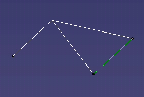
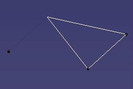
Example 1: Using a NON-MANIFOLD Body in a Join Operation
| Create a three-edge body (see figure on the right-hand side)
by assembling three concurrent wires (use CATTopWire then CATHybAssemble). This body is
made up of four vertices and three edges. It is clearly non-manifold. You can check
this by using the CATBody::GetCellsHighestDimension method. If you try to join the
highlighted body (a line) with the three-edge body by using the Join interactive command,
you will get the message:
"Update error: Non Manifold Body".
|
 |
| Now, if you try to remove the edge that makes the resulting
body non-manifold (use the "Sub-Elements to Remove" tab in the "Join Definition" dialog
box), you will get the message: "Bad topology".
This message tells you that the sub-element to be deleted is not fully
contained into a domain. Actually, it shares a vertex with two other wires. You
cannot go further in your operation, you must rebuild the initial body to make it manifold
or divide it into manifold domains as indicated above. In this
case, the best would consist in dividing the body into three single-edge wires not sharing
any vertices. |
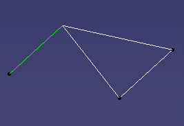 |
Example 2: Using a MANIFOLD Body in a Join Operation (to be
compared with Example 1)
| Given a three-edge manifold body looking like the one above
but made up of three wires and six vertices, if you try to join the highlighted body (a
line) with the three-edge body, you will get also the message:
"Update error: Non Manifold Body".
But now, if you try to remove the edge that makes the resulting body non-manifold (use
the "Sub-Elements to Remove" tab in the "Join Definition" dialog box), CATIA will remove it
and the join operation will complete. |
 |
| When you try to create a non-manifold body by
using the Sketcher commands, the created body will be non-manifold-like, but actually it
will be automatically divided into manifold domains so that further operations requiring to
remove unappropriate elements will be made easier. The Sketcher sticks to this strategy.
|
[Top]
In Short
-
The body is a set a domains, that contains connected cells , that are bounded by domains of lower
dimensions,
-
Rules are established to provide an unique decomposition of the body.
-
The following diagram summarizes the relations between the domains and the cells. The arrow
domain->cell represents the relation 'is composed of'. The arrow cell->domain represents the
relation 'is bounded by'.
Fig13: Topological objects diagram
 |
|
[Top]
References
History
| Version: 1 [Mar 2000] |
Document created |
| [Top] |
Copyright © 2000, Dassault Systèmes. All rights reserved.