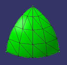
Fig 1. shows an example of triangles generation on a quarter of hemisphere.
Geometric Modeler |
Tessellation |
TessellationA way to discretize the geometry |
| Use Case | ||
AbstractThis article discusses the CAATesBody use case. This tutorial explains how to use the a Tessellation operator. |
This use case is intended to help you use the tessellation classes. The article first recalls the parameters that are used to tune the tessellation process, then explains how to use a tessellation operator to tessellate an object.
[Top]
The tessellation computes a geometric discretization from geometric curves [3], surfaces [4], or topological bodies, edges, or faces [1,2]. The results of their tessellation can then be used by applications which need to work with discretized data, such as visualization, mesh, or numerical control applications.
 |
The surfaces, faces, and the skin of the topological bodies
are paved with triangles. The curves and topological edges are discretized
with linear segments called bars. The extremities of the bars are called
points.
Fig 1. shows an example of triangles generation on a quarter of hemisphere. |
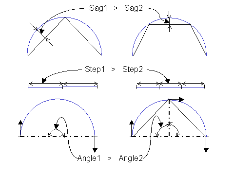
Three parameters tune the tessellation result.
By default, Step is infinite (in this case, it is not taken into account), and Angle is set to Pi/2.
 |
The Sag parameter takes the curvature of the objects into account. A lower sag creates bars that are "nearer" the object to tessellate. The Step acts on the length of the generated bars. A higher step generates longer bars. Now, imagine a semicircle whose radius is less than the Sag value and than the Step/Pi. If the tessellation only takes into account these two prameters, it would ignore this object. The Angle parameter allows you to catch the semicircle: the tessellation operator will create a new point as soon as the angle between the tangent at the extremities of the bars is more than Angle. In the figure Angle is set to Pi/2. |
Note: The parameter values are indicative values that can be sometimes locally overhang. Moreover, for a triangle discretization, the criteria are checked for the bars, not for all the points of the triangle interior.
[Top]
The tessellation of an object is made by the use of specific operators. There is an operator per type of object to tessellate:
They are built on the same scheme, which is the general scheme of a CGM operator. To use it:
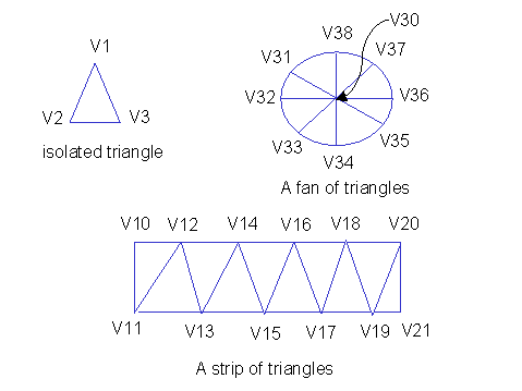
The results for curves and topological edges are given by the means of an array of computed points. The results for surfaces, topological faces and bodies are given as isolated triangles, strips of triangles, fans of triangles, the last two being provided for minimizing the memory size. Exceptionally, polygons are returned. In other words, the tessellation process outputs as few triangles as possible. In peculiar, if you tessellate a cube, no isolated triangles are output.
 |
An isolated triangle is defined by its three points (V1,V2,V3). A fan of triangles is a list of triangles, such that the first point of the list with any two consecutive points define a triangle. A strip of triangles is a list of points, such that any three consecutive points define a triangle. |
The algorithm tries, as far as possible, to return the triangles as strips or fans. But it happens that it returns them as isolated triangles, although it could find strips or fans. In some rare cases, polygons can be returned if the algorithm failed to tessellate them.
 |
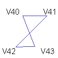
In case of some perturbed surface, the tessellation can lead to a rare configuration as in Fig 4. The polygon (V40, V41, V42, V43) represents a 3D twisted area, and fails to be expressed in terms of triangles. |
As many tessellation objects can be generated, the results of a tessellation operator are retrieved by the mean of iterators, one iterator per object type:
| generated object | Iterator name |
| points | CATTessPointIter |
| triangles | CATTessTrianIter |
| strips | CATTessStripeIter |
| fans | CATTessFanIter |
| polygons | CATTessPolyIter |
These iterators are all built on the same scheme. To use them:
[Top]
CAATesBody is a use case of the CAATessellation.edu framework that illustrates Tessellation framework capabilities.
[Top]
This use case creates a body representing a quarter of hemisphere. Then it defines a tessellation operator, runs it, and uses the results to create lines representing the generated bars. Finally, it clears the environment.
[Top]
To launch CAATesBody, you will need to set up the build time environment, then compile CAATesBody.m along with its prerequisites, set up the run time environment, and then execute the use case [5].
If you simply type CAATesBody with no argument, the use case executes, but doesn't save the result in an NCGM file. If you want to save this result, provide the full pathname of the NCGM file to create. For example:
CAATesBody e:\Tessellation.NCGMCAATesBody /u/Tessellation.NCGMThis NCGM file can be displayed using the CAAGemBrowser use case [6].
[Top]
The CAATesBody use case is made of a main named CAATesBody.cpp located in the CAATesBody.m module of the CAATessellation.edu framework:
| Windows | InstallRootDirectory\CAATessellation.edu\CAATesBody.m\ |
| Unix | InstallRootDirectory/CAATessellation.edu/CAATesBody.m/ |
where InstallRootDirectory is the directory where the CAA CD-ROM
is installed.
[Top]
There are five logical sections in CAATesBody;
[Top]
The geometry factory (CATGeoFactory) creates and manages all the CATICGMObject. This creation is done by the global function ::CATCreateCGMContainer. Notice that the factory can be defined by reading a NCGM file that was previously stored. In that case, the global function ::CATLoadCGMContainer must be used.
CATGeoFactory* piGeomFactory = ::CATCreateCGMContainer() ; if (NULL==piGeomFactory) return (1); |
[Top]
The body is created on the boundary of a geometric sphere (limited to a quarter of hemisphere).
The geometry is created by the CreateSphere method of CATGeoFactory. The body is created by the topological operator CATTopSkin. To use the operator:
NULL in the operator data. So that the
journal is not filled.[Top]
In this use case piBody is the pointer to the body to tessellate.
 //
 // create the operator
 double sag   = 0.2;
 CATBodyTessellator * pTessellator = new CATBodyTessellator(piBody,sag);
 if (NULL!=pTessellator)
 {
 pTessellator -> Run();

 //
 // Get the results
 //
 CATBoolean isPlanar=FALSE;
 CATTessPointIter *    pVertices  = NULL;
 CATTessStripeIter *   pStrips    = NULL;
 CATTessFanIter *      pFans      = NULL;
 CATTessPolyIter *     pPolygons  = NULL;
 CATTessTrianIter *    pTriangles = NULL;

 // Retrieve all the body faces.
 //
 CATLISTP(CATCell) faces;
 piBody->GetAllCells( faces,2); // faces are cells of dimension 2
 int numberOfFaces = faces.Size();
 // Scan  the result for one face
 for (int i=1 ; i<=numberOfFaces ; i++)
 {
   //
   // for each face, retrieve the tessellation results.
   //
   CATFace * piFace = (CATFace*) faces[i];
   pTessellator -> GetFace(piFace,
                           isPlanar,
                           &pVertices,
                           &pStrips,
                           &pFans,
                           &pPolygons,
                           &pTriangles);
    // use the results (see Using the Iterators to Retrieve the Results)
    //  ...... //
 }
 //
 // delete the operator
 delete pTessellator;
 pTessellator = NULL;
}
|
The operator pTesselator is created with the body to tessellate and the requested sag value. Then, call the Run method on the operator . The results are retrieved by dedicated iterators, allocated by the GetFace method. These iterators are deleted at the operator deletion.
[Top]
Now, the following section explains how to use these iterators. Results can be retrieved in one shot: in this case, the arrays, such as aCoord and aNuPts must be allocated and deallocated by the caller. The use case shows how to use the retrieved tessellation results in order to create geometric lines, but only the strips case is detailed here.
CATTessStripeIter
iterator
float  (* aCoord)[3]= NULL;
int * aNuPts        = NULL;
CATLine * piLn      = NULL;
//
// Points (in one shot)
//
if(NULL != pVertices)
{
   long nbp=pVertices->GetNbPoint();
   aCoord = new float[nbp][3];
   pVertices->GetPointXyzAll(aCoord); // all the coordinates in one shot
}
//
// strips (one by one)
//
if(NULL != pStrips)
{
  // size of the maximum allocation: use the iterator
  long nbs=0;
  while (0==(pStrips->IsExhausted()))       // last strip?
  {
    nbs=CATMax(nbs,pStrips->GetStriNbPts()); // the result of the current strip
    pStrips->GoToNext();                     // next strip
  }

  //
  // allocation
  //
  aNuPts=new int[nbs];
  //
  // from the beginning again to retrieve the results
  //
  pStrips->Reset();                          //initialize the strip iterator
  while (0==(pStrips->IsExhausted()))        // last one?
  {
    nbs=pStrips->GetStriNbPts();
    pStrips->GetStriNuPts(aNuPts);
    // create some interior lines of the strip from the results
    for (int j=0;j<nbs-1;j++)
    {
    piLn= piGeomFactory->CreateLine(
      CATMathPoint(aCoord[aNuPts[j]][0],
                   aCoord[aNuPts[j]][1],
                   aCoord[aNuPts[j]][2]),
      CATMathPoint(aCoord[aNuPts[j+1]][0],
                   aCoord[aNuPts[j+1]][1],
                   aCoord[aNuPts[j+1]][2]) );
  }
  // ..... //
  pStrips->GoToNext();                      // next one
}
delete [] aNuPts;
aNuPts = NULL;
}
if (NULL!=aCoord) delete [] aCoord;
aCoord = NULL;
|
[Top]
To save the model in a file, the ::CATSaveCGMContainer global function is used. Notice that in the use case, the save is conditioned by an input parameter representing the file inside which the model must be saved.
The use case ends with the closure of the geometry factory, done by the ::CATCloseCGMContainer global function.
 if(1==toStore)
 {
#ifdef _WINDOWS_SOURCE
   ofstream filetowrite(pfileName, ios::binary ) ;
#else
   ofstream filetowrite(pfileName,ios::out,filebuf::openprot) ;
#endif

   ::CATSaveCGMContainer(piGeomFactory,filetowrite);
   filetowrite.close();
 }

 //
 // Closes the container
 //
 ::CATCloseCGMContainer(piGeomFactory);
|
[Top]
[Top]
| Version: 1.1 [Oct 2000] | Configuration in the CATTopSkin operator |
| Version: 1 [Jan 2000] | Document created |
| [Top] | |
Copyright © 2000, Dassault Systèmes. All rights reserved.