3D PLM Enterprise Architecture |
User Interface - Frame |
Application Frame OverviewThe basics of interactivity |
| Technical Article | ||
AbstractThis article explains which paradigms CAA V5 uses to show objects and let end users play with them.
|
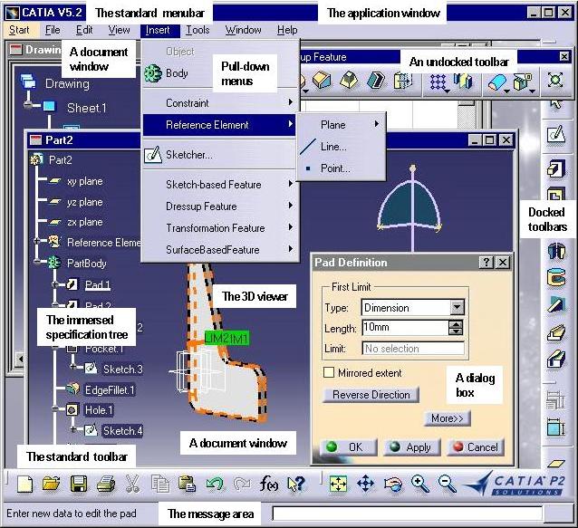
The CAA V5 application window is the host for all CAA V5 documents. As an MDI (Multiple Document Interface) application window, it can display several document windows at the same time as child windows of its application window, one document window, and thus one document, being active at the same time. Have a look at the screen shot below.
It shows the application window that contains two document windows. It shows also a palette of the tools available to work on the active document. This is a Part document, and its window contains the 3D part, and the part's specification tree as a 2D graph immersed into the 3D viewer displayed in the document window. The active document being a Part document, the tools available are those dedicated to parts. They are made of commands you can find in pull-down menus and toolbars. The active command being dedicated to pad definition, it displays a dialog box to enable the end user to enter its own parameters to define or modify the pad being edited.
Which are the objects that make all we have described above work, and how do they relate to each other? Which interfaces should they implement? This is the purpose of this article. These main objects are:
Most of these objects are detailed in the technical article entitled "The Frame Objects of the V5 Interactive Application" [1].
[Top]
It contains the document windows, which cannot escape from it. They can just move inside its frame. In addition, the application window holds the menus and toolbars, a message area, and possibly a power input keyboard.
The application window is usually not customizable, and is simply retrieved and used as is in applications, for example to set it as the parent window of document windows or dialog boxes [1].
[Top]
It is displayed inside the application window [1], and shows a document. It provides a view, also called presentation, of the document. Several windows can be displayed at the same time, some of them possibly displaying the same document.
The document window is the locus where the document can be edited. As a result, if several windows display the same document, modifying the document in one of these windows modifies the other windows, thanks to the MVC (Model View Controller) paradigm implemented by CAA V5.
Default document window classes are supplied: CATGraphAnd2DWindow for 2D documents, and CATGraphAnd3DWindow for 3D documents. They can display a specification tree of the document in addition to the 2D or 3D view. A customized document window can be created [2].
[Top]
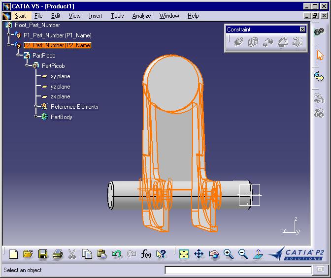
As for any MDI application, the CAA V5 application window can contain several windows to several documents, compared to a SDI application whose application window can contain only one document window at a time. But rather than supporting monolithic documents, CAA V5 supports also compound documents, that is documents containing other documents. This means that documents can be pointed (linked), or contained (embedded) by other documents of different types, and can themselves point to or contain other documents. For example, a Product document can contain several Part documents, placed in space at appropriate locations and linked together to play their role in the part's assembly.
When you open an existing Product document, the Product document's menus and toolbars making the workshop and the current workbench are made available, such as the File and Analyze menus, and the Constraint toolbar.
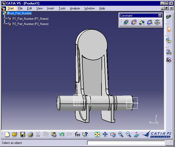
When you double click on one of the parts making up the assembly, for example here on P2 part, the selected part becomes the UI-active object. The menus and toolbars change to those dedicated to Part documents, such as the File and Insert menus, and the Sketch-based Features toolbar, and you can work on this part using these tools.
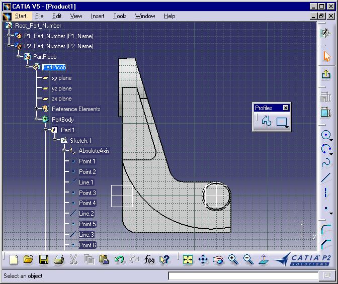
You can remark that the active document is a Product displayed in a Product window, but inside this window, the active object is a Part and since this active object is a document, the Product workshop and workbench are replaced by the Part workshop. The Part is called the UI-active object in the Product document, UI standing for User Interface. Any document that can be included into another document is a UI-activable object, but there is one UI-active object at a time. By extension, we can say that the Part document activated in a Part document window is itself the UI-active object. Moreover, some object which are not documents can be UI-activable. This is for example the case for sketches, which can neither be created using the New command, nor opened from or saved to a file. Nevertheless, when you double click on a sketch, or when you create a new sketch by dragging the Sketcher icon onto a reference plane, the sketcher workshop is made active and replaces the Part workshop though the sketch is not a document.
When you double click on a sketch in this part, for example in the specification tree, you change the 3D window into a 2D sketch window, and change the Part document menus and toolbars to the sketch menus and toolbars. The window remains the same, but the look and feel of it changes.
The Product and Part documents, as well as the sketch, load their own editing tools when you request to edit them, rather than opening another window. This is qualified as document-centric since the document remains displayed in the same window, and the editing tools change around the document to adapt to the type of the object being edited, even if this object is another document. This is to be opposed to the application-centric model in which the data to be edited is brought to another application for editing and is then taken back in its genuine context. With the document-centric model, the document remains displayed, and you edit a linked or contained document in the context of the linking or containing document without opening another window. For this reason, this is called edit-in-context. (OLE calls this in-place activation, and OpenDoc calls it in-place editing.)
[Top]
A CAA V5 document is associated with its own editing tools gathered in a workshop. Editing tools are commands that you arrange in menus and toolbars that make up the workshop. Some menus and the standard toolbar are independent from the type of the active document. They gather commands such as New, Open, or Print. They belong to the application window and are automatically added to any document's workshop. When a document is active, its own workshop is available in addition to these menus and to the standard toolbar. Changing the active document changes the active workshop if the new active document has a type different from the previous active one. Otherwise, the same workshop remains active, but possibly in a different configuration, in other words workbench. Add-ins allows you to add commands to workshops or workbenches without rebuilding their shared libraries and DLLs. To perform the appropriate transition between these two workbenches, the application should know what to do.
[Top]
You often want to group commands according to a given set of tasks they are related to. A handy means is to create as many toolbars as sets of tasks you define for your document, and let the end user select the toolbars to be displayed and those to be hidden. For example, in a text processor, you could group all the commands related to the text editing in a toolbar, those related to drawing in a second, and those related to tables in a third. These toolbars can be shown or hidden at end user will.
Nevertheless, in a complex application, the number of toolbars for a given document may dramatically increase, and you may want to make available to the end user only the toolbars dedicated to a given process at a time. To each process corresponds a set of toolbars and menu items, and changing the current process changes the available set of toolbars and menus while remaining in the same workshop.
For example, in a car repair workshop, you could imagine that the workshop is organized for engine tuning, engine maintenance, and engine repair. The workshop thus includes three workbenches, one equipped with tuning appliances, the other with equipment dedicated to changing spark plugs, oil filters, exhaust pipes, and engine sump draining, and the third with heavy equipment to repair engines. The same can happen in a CAD application, with different workbenches to work on a 3D model, such as a surface workbench, a solid feature workbench, and an analysis workbench, each of these workbenches providing a given usage configuration of the workshop dedicated to a specific process.
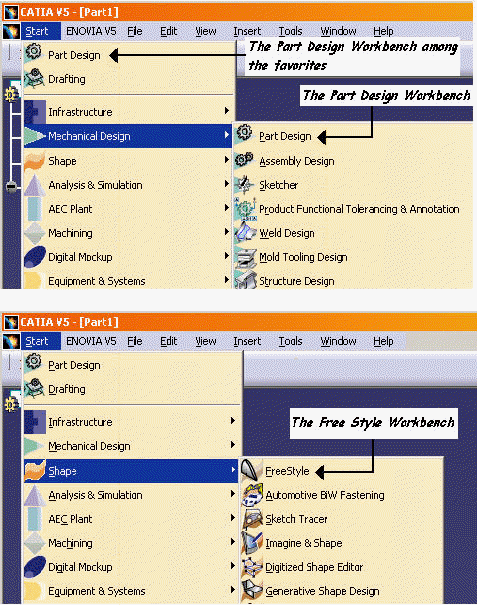
One workbench only is available at a time, and it makes sense to have two workbenches at least in a workshop. Otherwise, the workshop is also seen as a workbench. The end user selects the workbenches using the Start menu. For example, the Part document's workshop includes a Part Design workbench to create shapes, and a Free Style workbench to create curves and surfaces, and to modify and analyze shapes. This enables for a process-centric user interface.
To create a workbench, refer to the use case [4]
[Top]
The workshop and the workbenches show commands arranged in menus and toolbars. Both can be extended by add-ins. An add-in is made of one or several toolbars and menu items added to the workshop or workbench after it was created. This allows for smooth extensions, without the need of rebuilding any shared library or DLL, except the one for the add-in. Once created, the add-in is part of the workshop or workbench to which it belongs. To enable for add-ins, workshops and workbenches expose an interface including the workshop or workbench identifier. For example, assume that a workbench identifier is ShapeDesign. The interface this workbench exposes should be named CATIShapeDesignAddin. Creating and add-in is described in the use case [4]
[Top]
The structure of the workshop associated with the (document) UI-active object is described by the following picture.
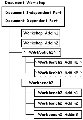 |
The workshop is made up of commands that are document independent,
such as New and Open in the File menu. These commands are group together in
an entity called General workshop. These commands are always available,
even if no document is active. The workshop also contains commands that are
document dependent. It can also include one or several add-ins. These
add-ins are part of the workshop, and are always available to the end user
when the workshop itself is available. A workshop can also include
workbenches. A workbench can in turn have its own add-ins. Like with
workshops, the add-ins are part of the workbench and are always available
to the end user when the workbench itself is available. Only one workbench
is available at a time. On the figure beside, Workbench2 is available,
along with its three add-ins. To have Workbench1 available, the end user
must select it in the Start menu. Then Workbench1 and its two add-ins
replace Workbench2 and its three add-ins.
In fact, the end user sees only workbenches, and all the commands available at a given time seem to be part of the workbench, even if the application programmer has put several commands in the workshop, several others in one or several of its add-ins, others in the workbench [8], and others again in one or several of the workbench add-ins [9]. The application programmer can also put commands in the workshop document independent part thanks to an add-in [10] |
[Top]
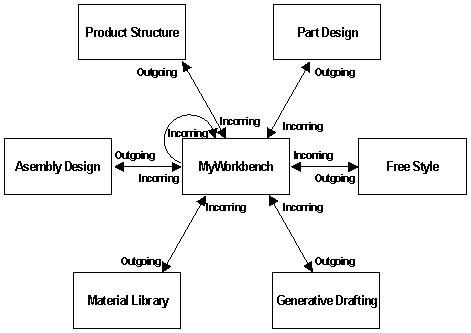
The Start menu offers to the end user a set of workbenches. Some of them are provided by Dassault Systèmes as part of its products and solutions, others are provided by third-parties, others can be home-made. From the end user viewpoint, all these workbenches are on the same level, even if some are used more than others. They can be selected by a simple click, even by error, and what happens depends on which document and workbench were active at the moment the end user clicks on another workbench. To perform the appropriate transition between these two workbenches, the application should know what to do. You will provide this knowledge using the CATIWorkbenchTransition interface you will implement either on the workbench, or on the workshop.
Transitions between workbenches can be classified in two main types, depending on whether the active document can be connected to a document of the type required by the selected workbench, or on the opposite has nothing to do with such as document. In the latter case, no document can be retrieved, and a new one should be created as if the end user had selected File->New. Otherwise, if, for example, a Part document is the active document and if the end user selects the Product Structure workbench, the end user intent may be to work at the product level rather than at the part level, meaning that the part was edited in-context. In this way, the product pointing to the part must be retrieved upwards in the Part specification tree and made the active one, while the Product Structure workbench is made available. The application should then be able to retrieve from the active document and using the selected workbench the document to make active, if it exists, whether this document contains or is contained by the active document. These two main cases are detailed below and can be classified into the following types of transitions.
For example, assume that the end user selects the Free Style workbench when a Part document and the Part Design workbench are active. Since the Free Style and Part Design workbenches belong to the same workshop and are both dedicated to Part documents, the active document remains active, and only the Free Style workbench is activated for that document.
For example, assume that the active document is a Part document and the active workbench is Part Design. The end user selects the Material Library workbench, which is for CATMaterial documents. Since a CATPart document cannot contain, or be contained by, a CATMaterial document, a new empty CATMaterial document is created in another window, and the selected workbench is activated.
For example, assume that the active document is a Product document and the active workbench is Assembly Design. The end user selects the Part Design workbench. It is associated to a Part document, usually pointed to or contained by a Product document. Two sub-cases arise:
For example, assume that the active document is a Part document and the active workbench is Part Design. The end user selects the Assembly Design workbench. It is associated to a Product document, which usually points to Part documents. The following sub-cases may arise:
You should consider these cases when you create a new workbench, and figure out the different cases that can happen depending on the type of the document this workbench is associated with. As you can see, and even transitions happen between workbenches, the associated document types always appear as a key point, and, as a consequence, the workshop dedicated to the document type that can often be used to implement once the same transitions involving all its workbenches. This can simplify a bit your job if you are not the workshop developer, since in this case you may have nothing to do.
Transitions from and to your workbench should be designed knowing that the application calls the workbenches and workshops involved in the transition in the following order:
Any of them can decide what to do when a transition occurs. The application calls them in that order until one of them decide. Its followers are then not called. If none decides, the transition manager deducts that the selected workbench belongs to the current workshop, and loads it.
To simplify the workbench interrelationships, each workbench must specify what should happen when it is selected, that is specify all its incoming transitions, even when it already is the active workshop and is selected by the end user. In addition, if your workbench is dedicated to a document type which can be pointed or contained by the document type to which the active document belongs, you should also implement the outgoing transitions to that workbench.
Refer to the use case [6]
Each command you want to make available in your workshop or workbench must have a command header [6]. The command header plays the role of your business card, which holds information such as your name, your company, your function within the company, the address where your company is located, your phone and fax numbers, and your e-mail id. This data is very useful to contact you when you are not here, and occupy a very small space. It stands for you in the pocket or the agenda of your friends, colleagues, and customers or contractors. Like a business card, the command header holds the necessary information to load the command, such as the command identifier, the name of the shared library in which the command's executable code is located, the name of the command class, and the data to pass to the command's code when this command becomes the current one. The command header has resources for each command to display, such as the command name shown to the end user, its tooltip displayed in a balloon, its help message, and its icon. This enables the workshop or workbench to be displayed, that is loaded in memory, without any of its commands being itself loaded, except the default one, spares memory space, and improves performance. The end user can see the icons in the toolbars, the items in the menu bar, can ask for help on a given command, without the command being loaded. It's only when he/she clicks on the menu item or on the icon that the command code is actually loaded. In addition, the command header can manage the command availability [7] with respect to what the end user does, or what exists in the document .
What happens at run-time? The first time a document of the
type you designed is created, opened or double-clicked, the application, by
means of the CATApplicationFrame class instance, asks for the document's
workshop using the GetWorkshop(Name) method of the
CATIUIActivate interface implemented by the UI-activable object of your
document. GetWorkshop returns the workshop name, here Tools. Then
the application queries a pointer to the workshop factory interface, and
requests this factory to create an instance of the workshop class. This class
implements the CATIWorkshop interface which provides the methods
GetWorkshop to create and return an instance of the workshop,
GetCommands to instantiate the workshop's command headers, and
GetInterface to return the interface derived from
CATIWorkshopConfiguration and exposed by the workshop to allow for
workbenches. Once these methods have been called and the appropriate objects
created and returned to the CATApplicationFrame class instance, your
document is loaded and displayed in its window, and the workshop you've
designed for it is available. Then, for any created, opened or double-clicked
document of the same type, the same workshop object is used (GetWorkshop
is not called again). Nevertheless, a new set of command headers is created and
associated with the document to keep the workshop's status for the document.
The workshop status is the availability or unavailability of each command
depending on the document contents.
To be emphasized or explained:
CreateCommands
method of the object that creates the starter and arranges the layout[Top]
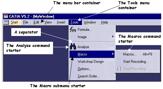
Usually, commands are organized in the menu bar, as shown below:
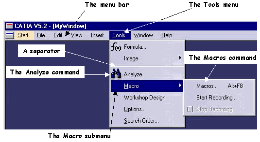
The menu bar contains menus, such as Tools, that contain themselves commands, such as Analyze, and possibly submenus, such as Macro, that are related to the menu topic. A submenu contains other commands and possibly submenus that are related with the submenu topic. For example, the Macro submenu contains the Macros, Start Recording, and Stop Recording commands. The commands are shown as menu items.
Commands are also contained in toolbars, like the Profiles toolbar shown below undocked, that is, as a separate dialog box:
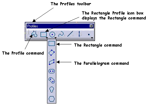
The Profiles toolbar contains commands shown using icons, such as the Profile command, and icon boxes, such as the icon box showing the Rectangle Profile command. An icon box contains a series of commands, but only shows either the first command in the icon box, or the last used. When the end user clicks the arrow located at the icon box right corner, the icon box opens, and the end user can select a command, such as the Parallelogram command. The icon box is closed, the Parallelogram command is launched and replaces the Rectangle command in the toolbar.
Note that the a command that is presented in a toolbar should also be the presented in the menu bar. This is a Windows 2000 recommendation to ensure that a keyboard shortcut is available for any command.
This is the end user view. Clicking on a menu item or an icon launches the command that stands behind. Let's have a look at the objects you'll deal with make this happen.
[Top]
When you want to arrange commands to propose them appropriately to the end user, you need to either create a workbench [3] or create an add-in [4] to an existing workshop or workbench. When you create such objects, you create in fact a containment tree structure to access to the commands. All these objects are therefore called accesses and their base class is CATCmdAccess. The objects that contain other objects are containers, and are instances of the CATCmdContainer class. The first container is the workshop or the workbench itself, and is an instance of the CATCmdWorshop or CATCmdWorkbench respectively, which both derive from CATCmdContainer. This container usually contains a menu container, and one or several toolbar containers. These containers can in turn contain other containers, such as a submenu or an icon box. At the lowest levels of this tree structure, you put the accesses for the commands. They are objects able to start the commands as soon as the end user clicks on the menu item or on the icon, and are therefore named command starters. Each command starter is associated with a command header that stands for the command and that holds the appropriate information about the command resources, such as the name displayed in the menu or the icon displayed in the toolbar, whether the command is available, and in which shared library the command code is located.
A container/contained tree structure is built. This tree structure represents both the way objects are related to each other, and how they are arranged in menus and toolbars in front of the end user. The figure above shows these objects for the menu bar. The workshop or workbench container contains a menu bar container that contains all the available menus, such as Tools. Tools is a container that contains its submenu containers, such as Macro. It also contains leaf objects for the commands, named command starters, such as the one for the Analyze command, that stand for the command in the tree structure, and that are associated with the command header. The submenu can also contain separators to help for command layout. The Macro submenu container contains in turn command starters, such as the one for Macros.
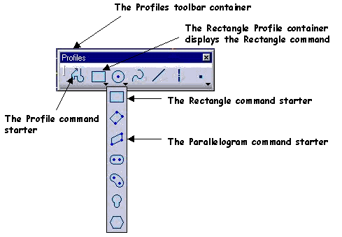
In the same way, the Profile toolbar is created as a container contained by the workshop, and that contains command starters such as for Profile, and other containers, such as Rectangle Profile which contains command starters to launch commands to create pseudo rectangle profiles, such as Rectangle or Parallelogram.
[Top]
In the Model View Controller paradigm,
The editor is described by the CATFrmEditor class [1]. This class manages the interactivity of the document. An instance of this class is created in the CATIEditor (ObjectModelerBase) interface implemented by the document.
[Top]
All these objects are created by the CATFrmEditor class instance associated with the document.
[Top]
A workshop is at a given time in a given context. What does this mean? Let's take an example to illustrate this. Imagine the active document is a Part document which includes a cylindric pad, as shown by the following figure.
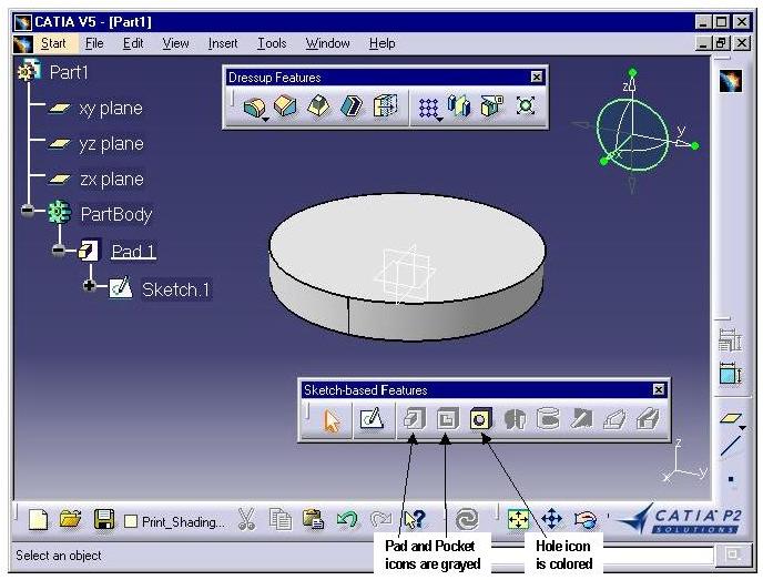
At this moment, the Pad and Pocket icons are displayed grayed and cannot be clicked. This is because no free sketch exists in the document that can be used to create a pad or a pocket, and thus these commands are unusable. It's safe then to make them unavailable. On the opposite, the Hole icon is colored, meaning that the Hole command is available, since you can create a hole in the pad by simply selecting a face and entering the hole definition parameters in the dialog box displayed by the Hole command. Grayed and colored icons show clearly which commands are not available and which commands can be used at a given moment, depending on the document's context, that is often depending on what it contains. This prevents from mistakes and end user errors the client application should handle with additional code and error messages. When you change the active document, the workshop retrieves the document's context and displays as gray the icons of the unavailable commands in this context.
This behavior is managed by the CATFrmEditor class instance associated with the document. This object contains the list of all the command headers defined for a type of UI-active objects. Refer to the "Life Cycle Management" section in the article [6].
[Top]
The CAA V5 application window includes commands which are common to all documents in menus and in the standard toolbar. Each document type is associated with a workshop which includes commands arranged in menus and toolbars which are added to the common menus and to the standard toolbar. Changing the active document to another document changes the active workshop if the new active document's type is different from the type of the previous document. A workshop can include workbenches to gather commands dedicated to specific tasks to structure the end user interface. One workbench only can be active at a time.
[Top]
| Version: 1 [Jan 2000] | Document created |
| Version: 2 [Fev 2003] | Document updated |
| [Top] | |
Copyright © 2000, Dassault Systèmes. All rights reserved.