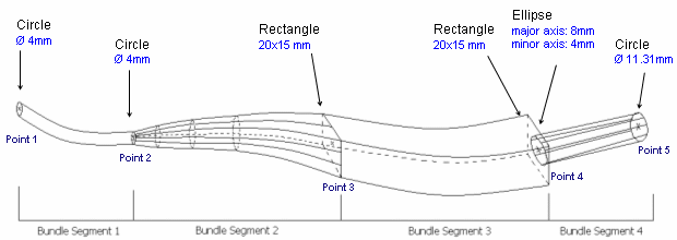
The aim of this functionality is to refine bundle segment geometry in order to accurately represent its shape. It also displays an overall volume close to reality. This applies when:
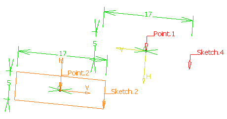
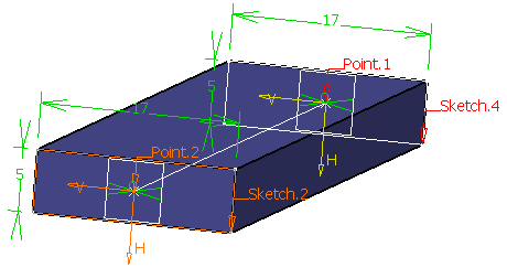
You can create different profiles, including rectangular and elliptical profiles, within the same branch. Profiles can then be rotated and the bundle segment shape can be based on this rotated profile.
This only applies to bundle segments within multi-branchable documents.
![]()
Multi-profile branch options are used to know how to update the parameters of the profile when the profile area is directly modified or updated after wire routing.
Designing Your Harness from Scratch
![]()
-
Create a geometrical bundle using Geometrical Bundle
 .
. -
Click Multi-Branchable Document
 and then close the dialog box that opens.
 -
Create few points to route the bundle segments.
Refer to Creating Construction Constraints for more information. -
Click Multi-Branchable Document
 again
and set branch parameters in the dialog box that opens.
again
and set branch parameters in the dialog box that opens.The Electrical Harness Assembly workbench switches to the Electrical Harness Installation workbench. The Branch Definition dialog box opens. 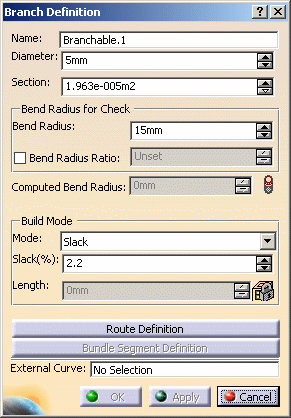
-
Click Route Definition:
- Select the objects of interest in the geometry area to define the route of the branch
- Click OK to validate your choice.
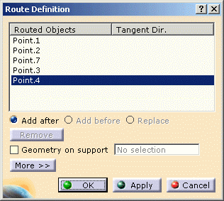
Note: A contextual menu allows you to directly access the Profile Management: 
The dialog box opens:
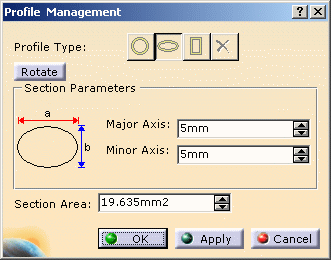
It lets you change the parameters described in next step.
-
Click Bundle Segment Definition in the Branch Definition dialog box.
The Bundle Segment Definition opens. - Add a branch point to create a second bundle segment.
- Select a bundle segment and change the Profile Type
to ellipse, for example.
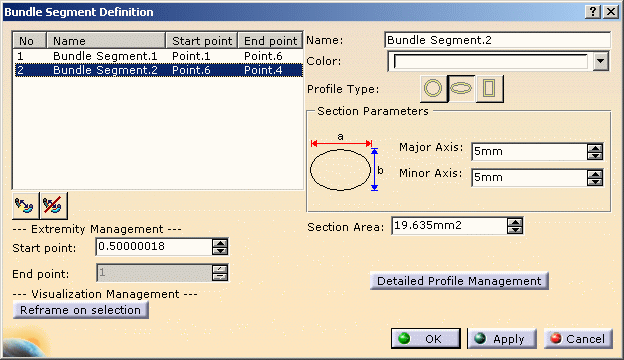
- Change the section parameters: 15mm for Major Axis, for example.
- Click Apply.

Section Parameters become unavailable as soon as you have entered information in the Detailed Profile Management. In this case the section shape can be different along the bundle segment.
Section Area becomes unavailable if the Set Area Constant check box is cleared.
The result looks like this:
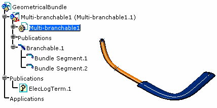
You can now refine the bundle segment profile. -
Click Detailed Profile Management.
The Profile Management dialog box opens: 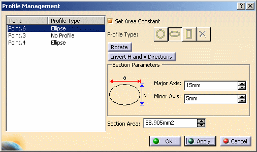
It lets you manage:
- The profile type at a given location
- A constant section all along the bundle segment
- The section area.
Profile Type
Constant Section
If the Set Area Constant check box is selected, the section parameters are calculated to keep the section constant all along the bundle segment: - If Major Axis or Minor Axis are modified at one point, the section parameters are updated at the other points or/and extremities to propagate this modification.
- If Length or Width are modified at one point, the section parameters are updated at the other points or/and extremities to propagate this modification.
 This check box is selected by default.
Section Area
Section parameters and area are linked together: if one changes, the others are automatically updated. Section Area is unavailable if the Set Area Constant check box is cleared.

For information on how section parameters are modified if the section area is changed, see bundle segment profile options. More About the Contextual Menu
A contextual menu is available from the Profile Management dialog box:
- On a bundle segment extremity, it allows you to:
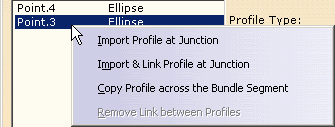
- Import Profile at Junction: copy the profile
of the connected bundle segment at the selected point, for
example:
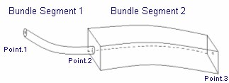
at Point.2 of Bundle Segment 2 (rectangular profile), you can import the profile of Bundle Segment 1 (circular profile):
As a result, you get a circular profile for Bundle Segment 1 instead of the original rectangular profile.
- Import and Link Profile at Junction: copy the
profile of the connected bundle segment at the selected point,
and link it to the profile itself, for example:
If the profile of Bundle Segment 1 at Point.2 (circular profile) is modified to ellipse, the profile of Bundle Segment 2 will automatically change to ellipse. - Copy Profile across the Bundle Segment: copy the profile type of the selected point to the other definition points of the bundle segment.
- Import Profile at Junction: copy the profile
of the connected bundle segment at the selected point, for
example:
- On any point which is not a bundle segment extremity, it allows
you to:
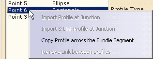
- Copy Profile across the Bundle Segment: copy the profile type of the selected point to the other definition points of the bundle segment.
- When profiles have been linked by a previous import and link,
it allows you to:
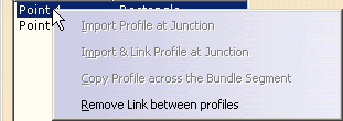
- Remove Links between Profiles: using this command does not change the profile at the selected point but unlinks the previously linked profiles.
- For extremity junctions where exactly two branchables meet, it
allows you to:
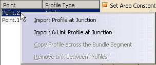
- Import Profile at Junction: copy the profile of the
connected bundle segment at the selected point. The profile will
be successfully copied. For example, at Point.2 of Bundle
Segment 2 (rectangular profile), you can import the
profile of Bundle Segment 1 (circular
profile):
As a result, you get a circular profile for Bundle Segment 1 instead of the original rectangular profile.
- Import and Link Profile at Junction: copy the profile of the connected bundle segment at the selected point, but the linking operation will not occur. For example: If the profile of Bundle Segment 1 at Point.2 (circular profile) is modified to ellipse, the profile of Bundle Segment 2 will automatically change to ellipse. However, segment 1 and segment 2 will remain as separate bundle segments.
- Import Profile at Junction: copy the profile of the
connected bundle segment at the selected point. The profile will
be successfully copied. For example, at Point.2 of Bundle
Segment 2 (rectangular profile), you can import the
profile of Bundle Segment 1 (circular
profile):
- For extremity junctions where more than two branchables meet:

- Import Profile at Junction/Import and Link Profile at Junction: Displays an error message, as there are more than one profiles to be imported.
- For extremity junctions when a new branchable is created:
- Import Profile at Junction/Import and Link Profile at Junction: Applicable only at the time of editing the branchable.
-
Click OK to validate your changes in the successive dialog boxes.
Adding/Removing Branch Points
![]()
When adding a branch point, the profiles at the new branch point are defined the following way:
- The profile at the second extremity of the first bundle segment is the same as the profile of the nearest previous profile.
- The profile at the first extremity of the second bundle segment is
the same as the profile of the nearest next profile.

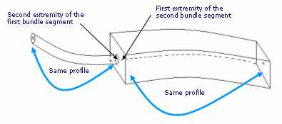
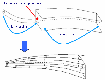
- And vice versa, when removing a branch point, the profiles at the
location of the branch point are removed:
Updating an Existing Harness
![]()
This task shows you how to re-compute harness bundle segments designed using the default circular profile option.
![]()
-
Set the bundle segment profile to Any Profile
 and select the option of
interest.
 -
Select the bundle segment you want to modify and click Branch Definition
 .
. -
Click Bundle Segment Definition in the Branch Definition dialog box.
Refer to the scenario above to change the profile. -
Click OK to validate your changes in the successive dialog boxes.
Protective Coverings and Adaptative Supports
- Protective coverings do not handle multiple profiles.
They can be applied to
circular profiles only.
The radius of the profile for tape is computed this way:Radius = sqrt(Max(Area)/PI)
wherePI= 3.14159...
andsqrt= square root. - Adaptive support formula behaves this way:
ELEC-SUPPORT-RADIUS = sqrt(Area_ave/PI)where
Area_aveis an average area along the bundle segment
Here, Area_ave = (Area 2 + Area 3) / 2

