They can be:
Defining Construction Points
-
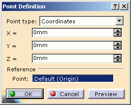
The Point Definition dialog box opens: 
-
Select Coordinates as Point Type:
The different types of points are: - Coordinates
- On curve
- On plane
- On surface
- Circle center
- Tangent on curve
- Between.
To know more about these options, refer to Creating Points.
See also Creating Planes, Creating Lines. -
Enter the respective coordinates for x, y, z.
-
Click OK to validate.
The point is added to the specification tree in the container named as Geometrical Set.
Defining Construction Points on a Part Surface
-
Double-click the part to activate Electrical Harness Installation.
-
Click Point
 .
. -
Select On surface in the Point Type list.
-
Select the surface where the point is to be created.
-
Optionally, select a reference point.

You can select an element to take its orientation as reference direction or a plane to take its normal as reference direction.
You can also use the contextual menu to specify the X, Y, Z components of the reference direction. -
Enter a distance along the reference direction to display a point.
-
Click OK to create the point.
The point (identified as Point.x) is added to the specification tree. -
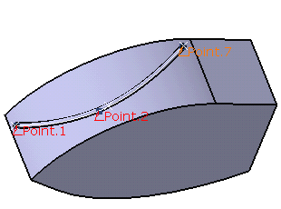
Repeat these steps for the other two points.
For more information refer to Creating Points.
See also Creating Planes, Creating Lines.
At the end the document looks like this:

