Specific products, resources, Manufacturing Assemblies and Manufacturing Kits can be selected from projects that are saved in the Manufacturing Hub. This section describes this procedure.
-
Open a process from the Manufacturing Hub.
-
Select Open Products, Resources, Manufacturing Assemblies and Manufacturing Kit from Manufacturing Hub
 in the Manufacturing Hub toolbar, or select Open Products,
Resources, Manufacturing Assemblies and Manufacturing Kit from the
Insert > Manufacturing Hub menu.
in the Manufacturing Hub toolbar, or select Open Products,
Resources, Manufacturing Assemblies and Manufacturing Kit from the
Insert > Manufacturing Hub menu. -
The PPR Hub - Select Product dialog box prompts for the type of object to be imported (product, resource, manufacturing assembly or manufacturing kit):
Note that only those object types that are currently available in the open project will be shown in the drop-down list above. If, for example, there are no manufacturing assemblies currently available in the project, Manufacturing Assembly will be omitted from the drop-down list. -
Right-click an object in the browser window to display a context menu containing a Properties command which allows read-only access to the object's Extended Properties Panel.
-
Loaded Manufacturing Kits and Assemblies appear under the Applications node in the Manufacturing Products folder as shown below. The parts and resources of the Kit are shown as children of the kit:
Selecting products based on volume
The Apply Volumetric Filter feature allows you to specify a bounding box, boundary clearance and boundary operator (i.e., Fully In, Fully Out, etc.,) to select products to load based on volume.
-
Select Open Products, Resources, Manufacturing Assemblies and Manufacturing Kit from Manufacturing Hub
. -
In the PPR Hub - Select Product dialog box, select the Apply Volumetric Filter checkbox:
The
 button becomes enabled.
 -
Select the loaded product and click
.
The current bounding box is displayed in the 3D viewer, and the
Specify Volume Filter Criteria dialog box is also displayed:
Modify the bounding box as needed and specify the desired Boundary Operator and Boundary Clearance accordingly in the Specify Volume Filter Criteria dialog.Using the Backdrop Viewer
To aid in defining the bounding box accurately, select Activate Backdrop Viewer to display a 3D window that contains a semi-transparent image of the entire assembly.
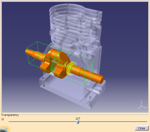
To display the backdrop image, a CGR representation of the end product must be specified for the 'graphicname' attribute of the product BOM node in the Manufacturing Hub project. This BOM node then must be selected as the BOM while loading data into DPM.
The corresponding CGR is displayed at the position specified on the BOM node with a default transparency of 50% as shown above.
- The transparency value specified for the backdrop is effective only when the Transparency Quality option is set to High (Alpha Blending). This option can be found in the Performance tab of Tools > Options > Display.
If bounding box co-ordinates are already defined in the Specify Volume Filter Criteria dialog box, this bounding box is drawn in the 3D viewer when Draw Bounding Box is clicked. If no bounding box values are defined, selecting any of the product data in the 3D viewer will display its bounding box. Note that the back drop image itself is not selectable. The user can also select the product data from the main window to display a bounding box in the viewer. The bounding box in the viewer can be manipulated to accurately define a specific volume of interest.
After a satisfactory bounding box has been defined, click Close to dismiss the viewer.
Volume filters can be loaded and saved with the Load and Save buttons as described in Defining and applying filters. -
Select OK.
Only those products that match the defined filter criteria are loaded. In addition, the tooltip for the
button now displays the volume filter criteria that has been set.
After the volume filter criteria has been defined, the Apply Volumetric Filter check box can be unchecked at any time so that the filter is not applied.
Product and resource behavior
Products and resources inserted from the Manufacturing Hub are made flexible by default. For details about flexible and rigid modes, please refer to Using Flexible Sub-Products in the DELMIA Product Structure Users Guide for more information.
Product and resource data loaded in in DPM will be visualized at the position specified in the Manufacturing Hub, and any modifications to the resource positions are saved back to the Manufacturing Hub when the process is saved. This default behavior can be modified to convert the flexible assembly to a rigid assembly via commands available in the product structure workbench. The flexible or rigid status of a product or resource is saved in the detailing when the process is saved back to the Manufacturing Hub.
Notes
- When a Manufacturing Kit is loaded, 3D states and positioned objects linked to any of its sub-components are also loaded. However, any 3D state or position information linked to the Manufacturing Kit itself is not loaded.
- When loading a Manufacturing Assembly in DPM, Manufacturing Assemblies defined as AST are not displayed in the browser.
- If data has been loaded in DPM using a resource-centric load (Please see Process and Resource Definition User's Guide: Advanced Task: resource-centric load), attempting to load a resource with the Import Products, Resources, Manufacturing Assemblies and Manufacturing Kit command, a warning message will be displayed to note that the resource load will continue without loading the processes associated to these resources.