This command computes and loads the products, resources and manufacturing assemblies that are assigned to processes that occur prior to the process that is currently loaded, based on the process sequence. This allows the current process be visualized within the manufacturing context.
-
Consider a project that has the following characteristics:
Task 1 processes both Sub Assy A-1 and Sub Assembly C. Task 2 processes Sub Assy A-2 and removes Sub Assembly C.
Task 3 has three operations which process Part A-3.a, Part A-3.b and Part A-3.c, respectively.
Process sequence
The computed manufacturing context is based on the process sequence defined for the project. Processes that occur before the loaded process in the sequence are considered when determining the manufacturing context, depending on the selected Manufacturing Hub Options.
The sequence for the project above looks like this:
-
Load a subprocess from the project (such as Op 3-b) in DPM:
-
When Op 3-b is loaded, all that can be seen in the PPR tree and 3D viewer are those products and resources associated to Op 3-b:
-
In many cases it would be advantageous to view the current process within the context of a manufacturing environment, where products from previous processes are also shown in the PPR tree and 3D viewer.
To load the products, resources and manufacturing assemblies associated with processes prior to the loaded process, Load Manufacturing Context
 in the Manufacturing Hub toolbar, or select the Insert >
Manufacturing Hub Object > Load Manufacturing Context menu
command:
in the Manufacturing Hub toolbar, or select the Insert >
Manufacturing Hub Object > Load Manufacturing Context menu
command:
-
The Manufacturing Context dialog box is displayed:
The Manufacturing Context dialog is used to specify whether a new Manufacturing Context is to be computed, as well as whether filters are to be applied to the Manufacturing Context.
-
Compute new Manufacturing Context
When enabled, a new Manufacturing Context will be computed. This option is checked by default if a Manufacturing Context has not yet been computed for the loaded document. -
Apply filters to Manufacturing Context
When enabled, user-defined filters based on product and resource attributes are applied to the Manufacturing Context. For information regarding how filters are defined, see Defining and Applying Filters, below.
-
-
When the command is completed, all products assigned to processes occurring prior the loaded process are loaded and shown in the PPR tree and 3D viewer, as shown below:
Defining and applying filters
User-defined filters based on product, resource and volumetric attributes may be applied to a Manufacturing Context.
-
After starting the Load Manufacturing Context command to display the Manufacturing Context dialog, click
 to select the filters to
be applied:
to select the filters to
be applied:
-
The Specify filter(s) to apply dialog box is displayed:
This dialog lists defined Product Attribute Filters, Resource Attribute and Volume Filters, and allows for filters to be added or edited, removed, loaded and saved.
Adding a new process attribute filter
-
Click Process Attribute Filter to highlight it.
-
Click the Add/Edit button
 to display the Specify Filter
Criteria dialog box:
to display the Specify Filter
Criteria dialog box:
This dialog specifies four different areas of criteria, defined as follows:
Plantype
Allows for the creation of a criterion for a given plantype or for all the plantypes of the filter scope (all product or all resource plantypes). Note that the values of the other fields of this panel are lost when the Plantype field is modified.Attribute
Lists the available attributes (all attributes with the "Display in Finder" option set in the Process Engineer Configuration manager) for the selected object type.Operator
Lists the different operators based on the the Attribute type selected (==, != LIKE, NOT LIKE for string attribute, ==, !=, >, <, >=, <= for numerical attributes).Value
Displays the value(s) to use for filtering for this attribute. By default, only one value can be defined per attribute. However, if the operator used for the attribute is = or !=, then several values may be specified (combine with an OR operator for the = operator and by and AND operator for the != operator). Three buttons are available to manage the value(s):Add allows the user to enter a value for the attribute. When clicking on the button, a panel will be displayed to enter the value (with the value field empty when opening the panel):
Depending on the selected attribute, this field may be either a list box, date editor or text field.
Remove allows the user to remove a value from the list. This button is enabled only when an entry in the value list is selected.
Edit allows for an existing value to be edited. This button is enabled only when an entry in the value list is selected. When clicking on the button, a panel will be displayed to update the value selected in the list:
Adding a new product or resource attribute filter
-
Click Product Attribute Filter or Resource Attribute Filter to highlight it.
-
Click the Add/Edit button
to display the Specify Filter
Criteria dialog box:
This dialog specifies four different areas of criteria, defined as follows:
Plantype
Allows for the creation of a criterion for a given plantype or for all the plantypes of the filter scope (all product or all resource plantypes). Note that the values of the other fields of this panel are lost when the Plantype field is modified.Attribute
Lists the available attributes (all attributes with the "Display in Finder" option set in the Process Engineer Configuration manager) for the selected object type.Operator
Lists the different operators based on the the Attribute type selected (==, != LIKE, NOT LIKE for string attribute, ==, !=, >, <, >=, <= for numerical attributes).Value
Displays the value(s) to use for filtering for this attribute. By default, only one value can be defined per attribute. However, if the operator used for the attribute is = or !=, then several values may be specified (combine with an OR operator for the = operator and by and AND operator for the != operator). Three buttons are available to manage the value(s):Add allows the user to enter a value for the attribute. When clicking on the button, a panel will be displayed to enter the value (with the value field empty when opening the panel):
Depending on the selected attribute, this field may be either a list box, date editor or text field.
Remove allows the user to remove a value from the list. This button is enabled only when an entry in the value list is selected.
Edit allows for an existing value to be edited. This button is enabled only when an entry in the value list is selected. When clicking on the button, a panel will be displayed to update the value selected in the list:
Adding a new volume filter
-
Click Volume Filter to highlight it.
-
Click the Add/Edit button
to display the Specify Filter
Criteria dialog box:
This dialog specifies four different areas of criteria, defined as follows:
Boundary Operator
May be set as Partly In, Partly Out, Full In or Fully Out.
When Fully In is selected, parts that are completely inside the bounding box are loaded. (Only Part1 will be loaded in the scenario above.)
When Fully Out is selected, parts that are completely outside the bounding box are loaded. (Only Part2 will be loaded in the scenario above.)
When Partly In is selected, parts that are either fully or partly inside the bounding box are loaded. (Parts 1, 3, 4 are loaded in the scenario above.)
When Partly Out is selected, parts that are either fully or partly outside the bounding box are loaded. (Parts 2, 3, 4 are loaded in the scenario above.)
Boundary Clearance
Specifies the clearance value. The clearance value enlarges or shrinks the bounding box in all directions, allowing for more or less data to be loaded in the computed manufacturing context.Reference Product
Specifies a product to be saved as a reference for the volume filter.When a reference product is used, any transformation in the position of the reference product is also applied to the volumetric filter bounding box. This maintains the focus on the volume of interest for filtering purposes, as the bounding box is shifted along with the product data.
Clicking the Reference Product button allows for the selection of a product in the PPR tree in the current document. After a selection is made, the instance name of the selected product is displayed in the corresponding text field. See Volume filter limitations below for restrictions on selecting reference product data.
Bounding Box Co-ordinates
Specifies the bounding box coordinates.If min and max values have been entered for the Bounding Box Coordinates, Draw Bounding Box can be used to draw a bounding box in the 3D viewer. This bounding box can be resized with the mouse pointer. When manipulated in this manner, the coordinates in the dialog are dynamically updated. The defined bounding box can also be edited by manually changing the coordinates in the dialog.
Once a Volume Filter is defined, another Volume Filter cannot be added, as only one volume is considered for filtering. For this reason, the Add/Edit button becomes disabled when the Volume Filter node is selected after a Volume Filter has already been defined.
Using the Backdrop Viewer
To aid in defining the bounding box accurately, select Activate Backdrop Viewer to display a 3D window that contains a semi-transparent image of the entire assembly.
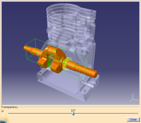 |
To display the backdrop image, a CGR representation of the end product must be specified for the 'graphicname' attribute of the product BOM node in the Manufacturing Hub project. This BOM node then must be selected as the BOM while loading data into DPM.
The corresponding CGR is displayed at the position specified on the BOM node with a default transparency of 50% as shown above.
|
If bounding box co-ordinates are already defined in the Specify Volume Filter Criteria dialog box, this bounding box is drawn in the 3D viewer when Draw Bounding Box is clicked. If no bounding box values are defined, selecting any of the product data in the 3D viewer will display its bounding box. Note that the back drop image itself is not selectable. The user can also select the product data from the main window to display a bounding box in the viewer. The bounding box in the viewer can be manipulated to accurately define a specific volume of interest.
After a satisfactory bounding box has been defined, click Close to dismiss the viewer.
Volume filter limitations
- This filter mechanism is not available to filter the manufacturing context when the Automatic computation of Manufacturing Context at load time option is enabled.
- Volumetric filtering is not available when loading a PPR project in DPM. It is available only to compute the manufacturing context after loading a project in DPM.
- The volume filter is applicable only for products and hence will filter only loaded products as part of the manufacturing context.
- The specification of a bounding box cannot be performed by selecting multiple parts. In addition, only one volumetric filter may be specified.
- Volumetric filtering is based on the bounding box information of a part. If a part is imported from ENOVIA, its bounding box information will also be imported and available in Process Engineer. However, if the part is newly created in Process Engineer, its bounding box information is not available and will not be filtered.
- The design position of a part is considered when applying a volumetric filter. Any 3D manufacturing positions defined in DPM are not considered for this purpose. In addition, when the bounding box is specified in DPM, only those parts whose design positions fall within the specified volume (as defined by the 3D Bounding Box) are loaded from Process Engineer.
- When saving filters against a process:
- Only one volume filter criteria can be saved against the process.
- The name of the volume filter must be unique.
- The filter saved against a process can be modified only if that process is currently loaded in DPM and the process is in an In-Work state.
- Resource data cannot be selected as a reference product
- A reference product may only be selected from product data loaded when the project the project was loaded.
Removing a filter
The Remove button
![]() is used to remove a criterion
or to empty a filter.
is used to remove a criterion
or to empty a filter.
To remove a criterion, select a criterion on the list and then click on the Remove button.
To empty a filter, select one of the two filter nodes (Product Attribute Filter or Resource Attribute Filter) and then click on the Remove button. This button is only enabled when a criterion/filter is selected.
Saving a filter
The Save button
![]() is used to save a filter for
reuse. Filters are saved in the database and available for any user from any machine via the Load button (described
below), and are assigned to the master Plantypeset of the current project.
is used to save a filter for
reuse. Filters are saved in the database and available for any user from any machine via the Load button (described
below), and are assigned to the master Plantypeset of the current project.
When the Save Filters dialog is displayed, use the checkboxes to select a filter type to save and enter the name of the filter(s) to save in the Name field:
 |
Volume filters may be saved against multiple processes. If a filter that has been saved against multiple processes is modified, the system will not allow it to be overwritten. It must be saved as a new filter with a different name.
Loading a saved filter
The Load filter button
![]() displays a panel combo boxes
listing the existing Process, Product, Resource and Volume filters for the master plantypeset of the current project. Select
a filter and click OK to load it.
displays a panel combo boxes
listing the existing Process, Product, Resource and Volume filters for the master plantypeset of the current project. Select
a filter and click OK to load it.
|
|
Delete buttons are available in this panel to delete a selected filter.
Notes
-
The Load Manufacturing Context command considers the following relations when computing the manufacturing context:
- Process processes product
- Process 1st processes product
- Process creates product
- Process removes product
- Process attaches resource
- Process detaches resource
- The manufacturing context can also be loaded automatically when the process is loaded from the Manufacturing Hub by enabling the Automatically compute Manufacturing Context at load time option on the Manufacturing Hub Options page.
-
Other options available on the Manufacturing Hub Options page determine how the previous processes are parsed, including whether:
- products are loaded only from processes that are at the same level of the current process, or from all levels
- child processes are considered
- "feed by another process" relations are considered
- unconstrained previous processes' products and resources are considered