Migrating Step by Step...

This task explains how to migrate a V4 files in to V5 files using PLM Batch.
  • In Tools > Options > General > Compatibility > Migration Batch tab, specify CATIE3DMigration in Migration Interface Name. For more information about this option refer to the Infrastructure User's Guide > Customizing > Migration Batch.
  • In Tools > Options > General > Compatibility > V4/V5 SPACE tab, select Isolated Solids Mock-up migration option as as PartBody . For more information about this option refer to the Infrastructure User's Guide > Customizing > V4/V5 SPACE.
  • In Tools > Options > General > Compatibility > Electrical tab, select the Shell Migration Mode to No, migrate geometry only. For more information about this option refer to the Infrastructure User's Guide > Customizing > Electrical Migration.
  • In Tools > Options > General > Compatibility > Electrical tab, Select Multi-branchable document option. For more information about this option refer to the Infrastructure User's Guide > Customizing > Electrical Migration.

Once the options are set up, you can launch the migration batch.

For more information on the Migration Batch, also refer to the V4 Integration User's Guide - User Tasks - Migration in Batch Mode.
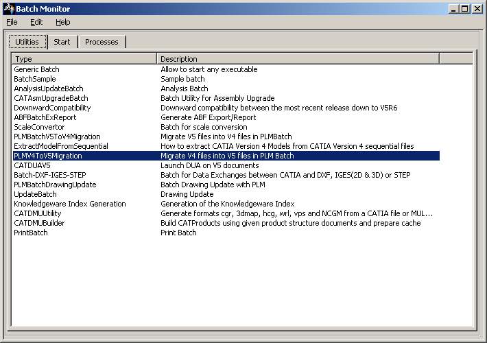
  1. Select Tools > Utility...
    The Batch Monitor window opens.

  2. Double-click the PLMV4TOV5Migration utility:

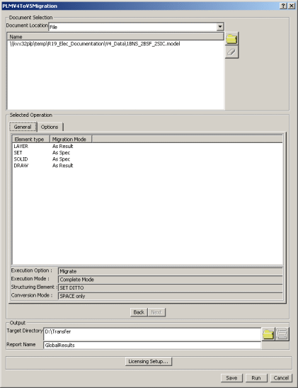
    The PLMV4TOV5Migration  dialog box opens. Set the migration batch environment and select the document to migrate.
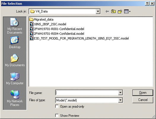
  3. Click on the Browse button in the Document Selection section. The File Selection dialog box opens.

  4. Click on the Member button.

  5. Select the file to be migrated from the File Selection dialog box and click Open.

  6. Click on the Change Target Directory button to specify the location of the Default target directory.

  7. Select the Target directory location and click Default button.
     

  8. Click OK in the File Selection dialog box.

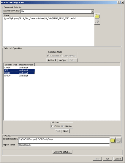
  9. Change the Migration mode of SET and SOLID Element types as As Spec by clicking on the As Spec button in the PLMV4ToV5Migration dialog box.
     

  10. Ensure that the Migrate radio button is checked.

  11. Browse and specify the location of the Target Directory in the Output section and click Next button.

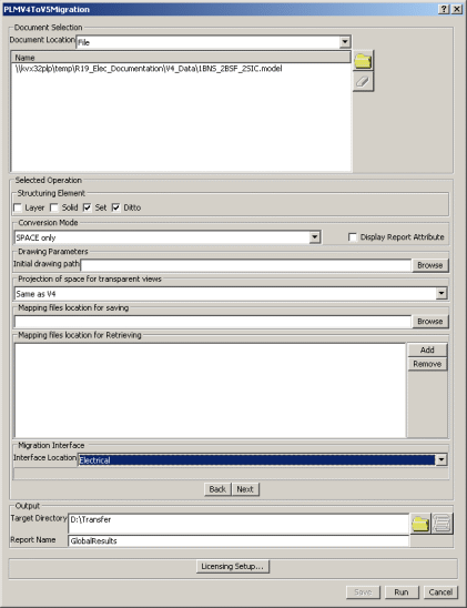
  12. Check the Set and Ditto check boxes in the Structuring Element section of the PLMV4ToV5Migration dialog box.

  13. Select the conversion mode as SPACE only from the Conversion mode list.

  14. Select the Interface location as Electrical in the Migration Interface section of the PLMV4ToV5Migration dialog box.

  15. Click Next.

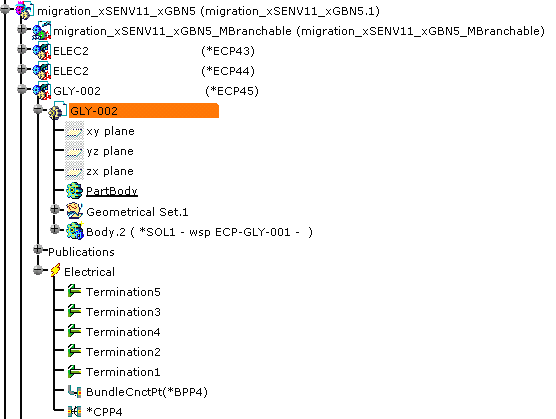
  16. Click Run. When the migration is performed, you get the xxxxx.CATProduct in your target directory, as well as CATParts and other documents.

  17. Open the xxxxx.CATProduct in CATIA V5.

  18. If need be, click updateall 

    You may have a message indicating a problem in the geometry area such as:
    • A twisted configuration on a bundle segment
      See Reference Information.
    • A fillet which needs to be modified
      Refer to Part Design User's Guide.
  1. For single insert connectors

    On V5 single insert connectors, the Representation of the connector connection point and the Contact constraint correspond to the migrated point of the CPP of the V4 SIC.
    Coincidence and Orientation constraints must be added, using Electrical Library.
    • Select the single insert connector as shown above: GLY-002
      See the specification tree below.
    • Using the right-mouse button, select Open in New Window to open the CATPart reference.
    • Double-click the *CPP4 in the Electrical container .
      The Connector Connection Point Definition dialog box opens:
      Refer to Electrical Library User's Guide - User Tasks - Defining Electrical Connection Points.
    • Select the face as Contact
    • Select the axis as Coincidence
      The result looks like this:
    • To use the Orientation constraint on this sample, you would need to create the geometry (such as a notch). Refer to Generative Shape Design User's Guide.
    • Click OK to validate the entry made.
      The publication has been generated.
    Specification Tree
    Repeat these steps for the other single insert connector:
    • Select ELEC2
      See the specification tree below.
    • Add the placement constraints to the *CPP5.
    • Using Electrical Library:
      Disconnect then re-connect the single insert connectors to create the mechanical constraints.
      Refer to Electrical Library User's Guide - User Tasks - Connecting/Disconnecting Devices.
    Specification Tree
  2. To connect a single insert connector to an equipment or connector shell

    You need to add a cavity connection point to the single insert connector and add or complete the definition of a cavity to the equipment or connector shell.
    • Adding a cavity connection point to the single insert connector
      • With the same methodology, select migration_ECP-GLY-001_xxSET2 for example and open it in new window.
      • Using Electrical Library, click Define Cavity Connection Point .
        Select the face for the Representation and the Contact, and the axis for the Coincidence.

        Refer to Electrical Library User's Guide - User Tasks - Defining Electrical Connection Points.

        The cavity connection point is created:

    • Completing the definition of a cavity to the equipment or connector shell: here a connector shell.
      • Select the connector shell: SHELL-GLY-002 and open it in new window.
        The cavities exist, but information is missing: you need to define the geometry of a pocket for example. Refer to Part Design User's Guide.

      • Then using Electrical Library, select GLY-01 and click Define Cavity .
        Select the pocket for the Representation, the face for the Contact, and the axis for the Coincidence.
        Repeat the operations for GLY-02.

        Refer to Electrical Library User's Guide - User Tasks - Defining Electrical Connection Points.

        The cavity definition is completed:

      • You now need to connect the single insert connector to the connector shell:
        Click Connect Electrical Devices
        Select the single insert connector
        then the connector shell cavity.
  3. For information about other elements to be added to complete the electrical data in V5, refer to About Device Migration.
    Also refer to Electrical Library User's Guide.

  • After the migration of electrical parts from V4 to V5, the part number is stored in the file name of the respective CATPart file.
    A screen-shot of the Properties dialog box, after the migration, showing the part number is as shown below:

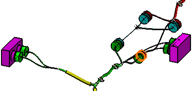
  • During the V4 to V5 migration, the migration mode in case of a flexible curve of the bundle segment is automatically switched to As Result when the migration in the As Spec mode causes modifications in shape or length. This change in migration results in a datum curve creation in V5 which is not editable. To to edit it you need to reroute the branch.
  • All the unnecessary files created during the migration process are deleted after the migration from V4 to V5.
  • If the V4 electrical data to be migrated to V5 contains protections, these are converted to internal protections, and are visible as Internal Protection under the Multibranchable node in the specification tree.
     
    The Multi-branchable document option under the Tools > Options > Compatibility > Electrical tab should be selected.