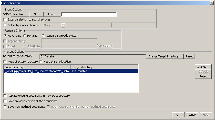
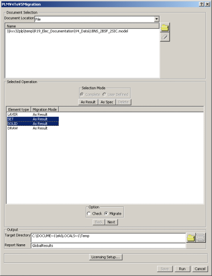
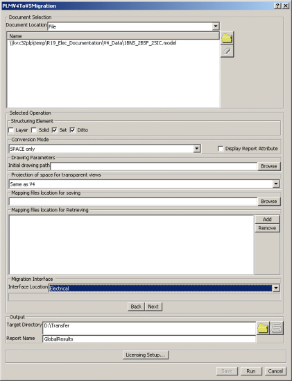
To perform the migration of the electrical data (geometry and technology), you first need to set up options for the:
These options can also be defined using:
- Tools > Options... > General > Compatibility > Migration Batch tab
- Tools > Options... > General > Compatibility > Electrical tab
- and Tools > Options > General > Compatibility > V4/V5 Space.
Refer to the Infrastructure User's Guide (Customizing Settings - General - Compatibility category).
![]()
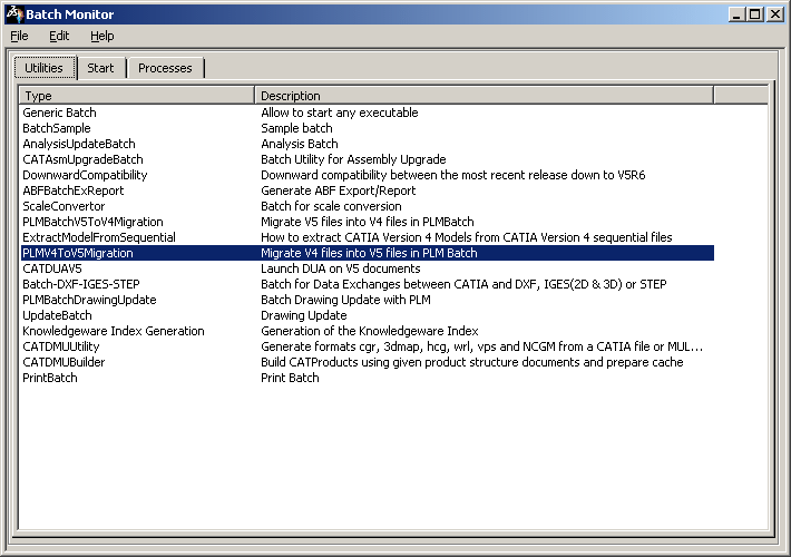
To do so, you need to access to the Batch Monitor:
Setting up the Electrical Migration Batch
|
|
|
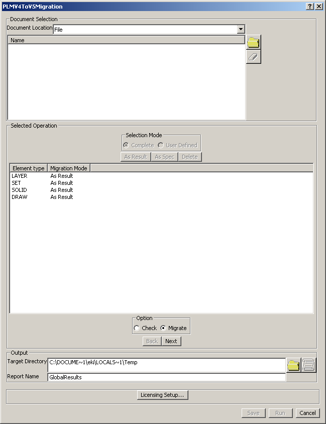
Insure that all objects are set to 'AsSpec'as the migration as the migration is not supported by V4 electrical elements. |
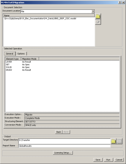
Setting up the Geometrical Bundle Migration Mode
-
Still in the Interactive Options dialog box, select the Electrical tab.
This tab lets you define whether or not you want:
-
Each GBN migrated as a product in a separate CATProduct:
in this case, select Product.
 By default, Product is selected.
-
Each GBN migrated as a component under the root product:
in this case, select Component.

Choosing the right migration mode option is important since it determines how geometrical bundles will be stored in ENOVIA LCA: - Migrating them as products lets you store them in ENOVIA LCA using Workpackage mode
- Migrating them as components lets you store them in ENOVIA LCA using Explode mode.
-
-
Select the option of interest.
Setting up the Bundle Segment Migration Mode
-
Still in the Electrical tab.
This tab lets you define whether or not you want:
-
Each V4 BNS of the GBN migrated to a separate CATPart:
in this case, select Bundle segments.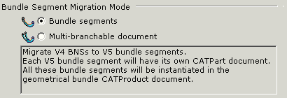
-
All the V4 BNSs of the GBN migrated to a single CATPart:
in this case, select Multi-branchable document.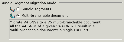
 Multi-branchable document is the default value.
It is recommended to use this option as it reduces the number of CATPart documents generated during the migration.
-
-
Select the option of interest.
Setting up Isolated Mock-Up Solids migration
-
Still in the Interactive Options dialog box, select the V4/V5 SPACE tab.
This tab lets you define an option for the Isolated Mock-up Solids migration:
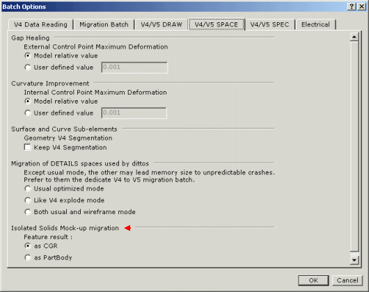
Isolated Mock-Up Solids (SolidM) means that they have no history nor specifications stored.
For the migration two options are available:
-
as CGR: the SolidM conversion as CGR means that you will only get the meshing view (visualization mode).
 as CGR is the default value.
 -
as PartBody: the SolidM conversion as PartBody means that you will be able to see the geometry of the solid to edit it.
Refer to V4/V5 SPACE tab in Infrastructure User's Guide.
(Customizing Settings - General - Compatibility category). -
-
Select as PartBody in the context of the electrical migration to be able to add technology.

-
Once you have selected your options, click OK to validate.
You are back in the MigrateV4ToV5 dialog box. -
Select a target directory (where the V5 documents will be created).
-
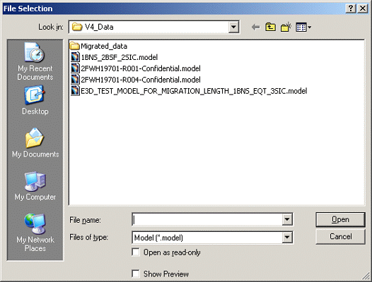
Select the V4 documents to be converted.
You are ready to migrate your V4 electrical data.
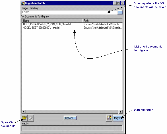 |
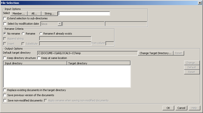
Select the files to migrate and the path for the result as explained in the utility documentation and run the batch.
