3D PLM Enterprise Architecture |
3D Visualization |
Understanding the Basics of the Visualization ProcessCreating and displaying representations in a viewer |
| Use Case | ||
AbstractThis article shows how to create a CAT3DFaceGP class instance to tesselate a torus and how to display it using a CAT3DCustomRep instance. |
This use case explains how to create representations, to set their graphic attributes, to compute their bounding sphere, and how to display them in a viewer.
[Top]
CAAVisBasicAppli is a use case of the CAAVisualization.edu framework that illustrates Vizualization framework capabilities.
[Top]
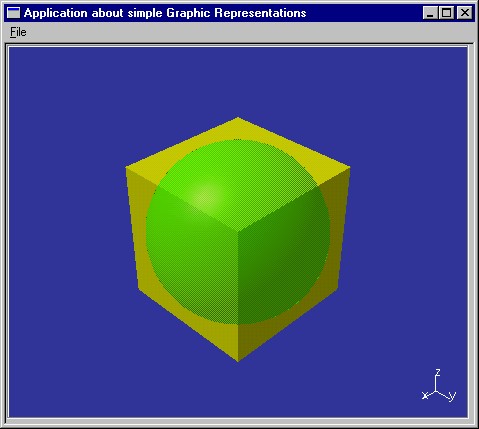
CAAVisBasicAppli includes an interactive application that displays a 3D navigation viewer in its document window. This viewer shows a simple model representation made of a cuboid and a sphere. They are displayed as soon as the application is launched.
[Top]
To launch CAAVisBasicAppli, you will need to set up the build time environment, then compile CAAVisBasicAppli along with its prerequisites, set up the run time environment, and then execute the use case [1].
[Top]
The CAAVisBasicAppli use case is made of two classes named CAAVisBasicApplication and CAAVisBasicWindow located in the CAAVisBasicAppli.m module of the CAAVisualization.edu framework:
| Windows | InstallRootDirectory\CAAVisualization.edu\CAAVisBasicAppli.m\ |
| Unix | InstallRootDirectory/CAAVisualization.edu/CAAVisBasicAppli.m/ |
where InstallRootDirectory is the directory where the CAA CD-ROM
is installed.
[Top]
| # | Step | Where |
|---|---|---|
| 1 | Create a 3D navigation viewer instance | CreateViewer method |
| 2 | Create a 3D representation bag | CreateModelRepresentation method |
| 3 | Create the cuboid 3D representations | CreateModelRepresentation method |
| 4 | Set graphic attributes to the representation | CreateModelRepresentation method |
| 5 | Compute the graphic representation bounding box | CreateModelRepresentation method |
| 6 | Add the representation to the representation bag | CreateModelRepresentation method |
| 7 | Display the representation bag and its children | VisualizeModel method |
Only the cuboid is taken as an example and described. All the methods belong to the CAAVisBasicWindow class.
[Top]
The 3D navigation viewer is an instance of the CATNavigation3DViewer
class. It is created in the CreateViewer method of the CAAVisBasicWindow
class that is called when the application is launched.
void CAAVisBasicWindow::CreateViewer()
{
  _p3DViewer = new CATNavigation3DViewer(this,
                                         "3DViewerId",
                                         CATDlgFraNoTitle,
                                         800, 450);
  _p3DViewer->SetBackgroundColor(0.2f,0.2f,0.6f);
  Attach4Sides(_p3DViewer);
}
|
The _pViewer pointer to the 3D navigation viewer is kept as a
data member of the CAAVisBAseView class. Its parameter are:
this |
The viewer parent in the dialog containment tree structure and in the command tree structure [a] |
3DViewer |
The viewer identifier |
CATDlgFraNoTitle |
The viewer has no title [b] |
850, 450 |
The viewer width and height expressed in pixels |
The SetBackGroundColor method sets the viewer background color
to a shade of blue. The Attach4Sides method attaches the four sides
of the viewer to those of the window. This makes the viewer occupy the whole
window space.
[Top]
void CAAVisBasicWindow::CreateModelRepresentation()
{
  _pTheModelToDisplay = new CAT3DBagRep();
...
|
The CreateModelRepresentation of CAAVisBasicWindow begins
by creating the representation bag to attach to the viewer.
[Top]
...
  CATMathPointf  Corner      (-20.f, -20.f,  0.f);
  CATMathVectorf FirstVector ( 20.f,   0.f,  0.f);
  CATMathVectorf SecondVector(  0.f,  20.f,  0.f);
  CATMathVectorf ThirdVector (  0.f,   0.f, 20.f);

  CAT3DCuboidRep * pCuboid = new CAT3DCuboidRep(Corner,
                                                FirstVector,
                                                SecondVector,
                                                ThirdVector);
...
|
The cuboid geometric components are created. These comprise a point and three vectors that define the three edges starting from this point. They are then passed to the CAT3DCuboidRep constructor.
[Top]
...
  if ( NULL != pCuboid )
  {
    pCuboid->SetColor(YELLOW);
...
|
The cuboid is now yellow.
[Top]
The graphic representation needs a bounding box to improve the display process.
... CATMathPoint Center = Corner + (FirstVector + SecondVector + ThirdVector)/2; float Radius = (float) Corner.DistanceTo(Center); CAT3DBoundingSphere BoundingSphere(Center,Radius); pCuboid->SetBoundingElement(BoundingSphere); ... |
This bounding box is sphere whose center is the cuboid center, and whose radius is the distance between this center and the point used as corner when defining the cuboid. The bounding box is used to decide whether the representation should be displayed with respect to the current viewpoint without interpreting the representation itself, thus increasing display performance.
[Top]
... _pTheModelToDisplay->AddChild(*pCuboid); } |
The created representation is added to the representation bag thanks to the AddChild
method.
[Top]
void CAAVisBasicWindow::VisualizeModel()
{
  if ( (NULL != _p3DViewer) && ( NULL != _pTheModelToDisplay) )
  {
    _p3DViewer->AddRep((CAT3DRep*)_pTheModelToDisplay);
    _p3DViewer->Draw();
  }
}
|
The representation bag is added to viewer, and the viewer is asked to draw itself.
[Top]
This use case shows the objects involved in the visualization process. A representation bag is first created to contain the other representations. Each representation is then created with its own geometric characteristics, can be assigned attributes, and its bounding sphere is computed. Each representation is added to the representation bag, and the bag is set to the viewer. Then the viewer is asked to draw itself.
[Top]
| [1] | Building and Launching a CAA V5 Use Case |
| [Top] | |
| Version: 1 [Mar 2000] | Document created |
| [Top] | |
Copyright © 2000, Dassault Systèmes. All rights reserved.