AbstractThis article shows how to create a CATSufacicRep class instance to visualize a set of CAT3DFaceGP and CAT3DLineGP and use some of the advanced capability of this class. |
This article shows how to create a CATSufacicRep class instance to visualize a set of CAT3DFaceGP and CAT3DLineGP and use some of the advanced capability of this class like the different topological slots available on the CATSurfacicRep, and the way to persistently store in a CGR file topological informations on graphic primitives.
[Top]
CAAVisBasics is a set of use cases of the CAAVisualization.edu framework that illustrates Vizualization framework capabilities.
[Top]
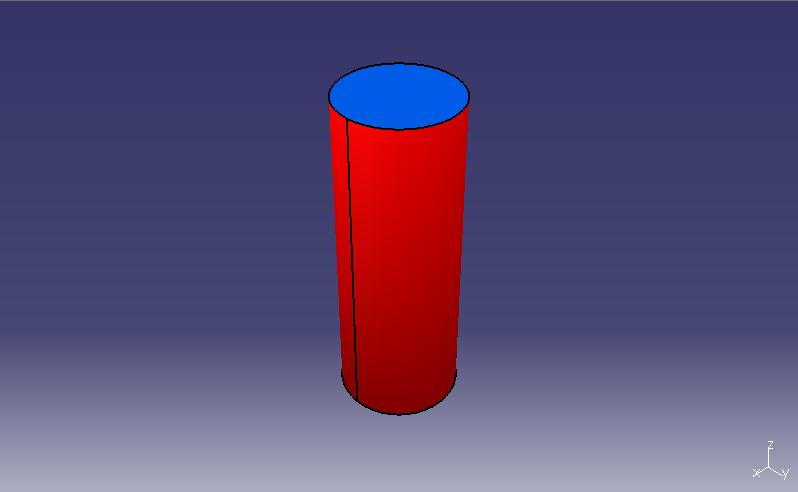
CAAVisBasics includes a MDI interactive application that displays viewers in its document windows. The VisuObjects menu allows the creation of a CATSurfacicRep class instance that contains the visualization of a cylinder. This article focuses on how to create the CATSurfacicRep representation associated with CAT3DFaceGP and CAT3DLineGP graphic primitives.
The cylinder is displayed in a 3D navigation viewer as soon as the corresponding menu is selected.
|
[Top]
To launch CAAVisBasics, you will need to set up the build time environment, then compile CAAVisBasics along with its prerequisites, set up the run time environment, and then execute the use case [1].
The torus is displayed in a 3D navigation viewer as soon as the application is launched.
[Top]
The CAAVisBasics use case is made of several classes located in the CAAVisBasics.m module of the CAAVisualization.edu framework:
| Windows | InstallRootDirectory\CAAVisualization.edu\CAAVisBasics.m\ |
| Unix | InstallRootDirectory/CAAVisualization.edu/CAAVisBasics.m/ |
where InstallRootDirectory is the directory where the CAA CD-ROM is
installed.
This use case deals with the following classes:
| CAAVisBaseApplication | Class for the interactive application that hosts the viewer |
| CAAVisBaseDocument | Class for the document base class |
| CAAVisBaseVisuObjectDocument | Class for the document that allows for specific visualization object creation |
| CAAVisBaseView | Class for the document window containing a viewer to display the document |
[Top]
This article does not focus on the details of tesselating a cylinder. A good sample that covers the subject of creating tesselated shapes using strip and fans triangles can be found here.
[Top]
| # | Step | Where |
|---|---|---|
| 1 | Create the graphic primitive and its associated bounding box | CreateSurfacicRep method of CAAVisBaseVisuObjectDocument |
| 2 | Associate topological information to the graphic primitives | CreateSurfacicRep method of CAAVisBaseVisuObjectDocument |
| 3 | Set graphic attributes to the graphic primitive | CreateSurfacicRep method of CAAVisBaseVisuObjectDocument |
| 4 | Creating the CATSurfacicRep representation | CreateSurfacicRep method of CAAVisBaseVisuObjectDocument |
| 5 | Associate the representation with the graphic primitive | CreateSurfacicRep method of CAAVisBaseVisuObjectDocument |
| 5 | Compute the representation bounding box | CreateSurfacicRep method of CAAVisBaseVisuObjectDocument |
| 6 | Display the created 3D representation | AddRepToViewer method of CATVisBaseView |
The cylinder is displayed when the CATSurfacicRep menu item contained in the VisuObjects
menu is selected. The cylinder creation and display is performed in the CAAVisBaseVisuObjectDocument constructor
that calls the CreateSurfacicRep and AddRepToViewer methods
respectively. These two methods are described below.
[Top]
The graphic primitive is created using the arrays computed in the code. Feel free to have a look at this part of the code that describes how to tesselate a cylinder.
void CAAVisBaseVisuObjectDocument::CreateSurfacicRep()
{
   // ...

   // We create the top face
   CAT3DPlanarFaceGP * topFace = new CAT3DPlanarFaceGP(  topVertices, nbFaceVertices*3,
                                                         normal,
                                                         triangleIndices,
                                                         nbTriangles,
                                                         stripIndices,
                                                         nbStrips,
                                                         nbStripVertices,
                                                         fanIndices,
                                                         nbFans,
                                                         nbFanVertices);

   // We create the line that bounds the face
   CAT3DLineGP * topLine = new CAT3DLineGP(topVertices, nbFaceVertices, ALLOCATE, LINE_LOOP);

   // ...

   // We create the body face
   CAT3DFaceGP * bodyFace = new CAT3DFaceGP( bodyVertices, 2*nbFaceVertices*3,
                                             bodyNormals,  2*nbFaceVertices*3,
                                             triangleIndices,
                                             nbTriangles,
                                             stripIndices,
                                             nbStrips,
                                             nbStripVertices,
                                             fanIndices,
                                             nbFans,
                                             nbFanVertices);

   // We create the lines that bounds the body
   CAT3DLineGP * bodyLine1 = new CAT3DLineGP(bodyLineVertices,     2, ALLOCATE, LINES);
   CAT3DLineGP * bodyLine2 = new CAT3DLineGP(&bodyLineVertices[6], 2, ALLOCATE, LINES);

   // ...
}
|
The CAT3DPlanarFaceGP graphic primitive used for the top and bottom faces of the cylinder
allows to create a planar face that only needs one normal definition instead of one normal for each vertex.
This allows for less memory consumption when creating planar faces.
The CAT3DLineGP graphic primitive used for the lines that bounds the top, bottom, and body faces
of the cylinder allows to create a line using an input set of vertices.
The bounding box and bounding sphere are generated automatically when a CAT3DFaceGP or CAT3DPlanarFaceGP is instancianted based on it's input set of vertices. Both classes inherit CAT3DBoundingGP which provides the following methods to retrieve the bounding element on such classes:
float * CAT3DBoundingGP::GetSphereCenter() |
Returns a 3 fields array containing the sphere center coordinates |
float CAT3DBoundingGP::GetSphereRadius() |
Gets the bounding sphere radius |
float * CAT3DBoundingGP::GetBoxCenter() |
Returns a 3 fields array containing the box center coordinates |
float * CAT3DBoundingGP::GetBoxDimensions() |
Returns a 3 fields array containing the half box spans coordinates. |
void CAT3DBoundingGP::ComputeBox() |
Forces the recomputation of the bounding sphere / box. |
[Top]
Persistent (in the CGR file) topological informations can be stored on CATGraphicPrimitives.
////////////////////////////////////////////////////////////////////////// // Topological informations // We can store topological informations on CATGraphicPrimitive objects // If the visualization data is saved as a CGR file, topological data will // be persistent in the CGR file ////////////////////////////////////////////////////////////////////////// CATMathPoint center(0,0,0); CATMathVector axis(0,0,1); CATMathPoint startPoint,endPoint; // Top face CATGraphicPrimitive * gp = topFace; CATVisMeasurableGP cylinderTop(gp); cylinderTop.SetCylinder(center,axis,radius); // Bottom face gp = bottomFace; CATVisMeasurableGP cylinderBottom(gp); cylinderBottom.SetCylinder(center,axis,radius); // Top line gp = topLine; CATVisMeasurableGP circleTop(gp); circleTop.SetCircle(center,axis,radius); // Bottom line gp = bottomLine; CATVisMeasurableGP circleBottom(gp); circleBottom.SetCircle(center,axis,radius); // Body face gp = bodyFace; CATVisMeasurableGP cylinderBody(gp); cylinderBody.SetCylinder(center,axis,radius); // Body line 1 gp = bodyLine1; startPoint.SetCoord(bodyLineVertices[0], bodyLineVertices[1], bodyLineVertices[2]); endPoint.SetCoord (bodyLineVertices[3], bodyLineVertices[4], bodyLineVertices[5]); CATVisMeasurableGP cylinderBodyLine1(gp); cylinderBodyLine1.SetLine(startPoint,endPoint); // Body line 2 gp = bodyLine2; startPoint.SetCoord(bodyLineVertices[6], bodyLineVertices[7], bodyLineVertices[8]); endPoint.SetCoord (bodyLineVertices[9], bodyLineVertices[10], bodyLineVertices[11]); CATVisMeasurableGP cylinderBodyLine2(gp); cylinderBodyLine2.SetLine(startPoint,endPoint); |
The CATVisMeasurableGP can be used in order to store topological informations on any CATGraphicPrimitive. See the CAA documentation for more details on which type of informations can be stored.
[Top]
// ... // We create the surfacic rep CATSurfacicRep * sRep = new CATSurfacicRep(); sRep->GetGraphicAttributeSet().SetType(3); // Specifies that this surfacic rep is a volume // ... |
The CATSurfacicRep is a complex visualization class. It handles graphic primitives topologicaly in order to provide custom drawing algorithms. See below for a list of topological slots available on the CATSurfacicRep. We also specifie that this CATSurfacicRep is a volume, which will allow for some drawing optimizations like backface culling
[Top]
// ... sRep->AddGeomFace(topFace, new CATGraphicAttributeSet(tmpAtt)); sRep->AddGeomFace(bottomFace, new CATGraphicAttributeSet(tmpAtt)); sRep->AddGeomFace(bodyFace, new CATGraphicAttributeSet(tmpAtt)); // ... sRep->AddGeomElt(CATBoundaryEdge, topLine, new CATGraphicAttributeSet(tmpAtt)); sRep->AddGeomElt(CATBoundaryEdge, bottomLine, new CATGraphicAttributeSet(tmpAtt)); sRep->AddGeomElt(CATInternalSmoothEdge, bodyLine1, new CATGraphicAttributeSet(tmpAtt)); sRep->AddGeomElt(CATInternalSmoothEdge, bodyLine2, new CATGraphicAttributeSet(tmpAtt)); // ... |
The main methods used for adding/retrieving graphic primitives to a CATSurfacicRep are the following (Please see the CAA documentation for the full list of methods available) :
HRESULT AddGeomFace(CAT3DFaceGP *face,CATGraphicAttributeSet *att) |
Adds a CAT3DFaceGP / CAT3DPlanarFaceGP and it corresponding graphic attribute to the surfacic rep. |
int GeomNumberOfFaces() |
Retrieves the number of faces owned by the surfacic rep. |
HRESULT AddGeomElt(const CATGeomType iType, CATGraphicPrimitive *iGP, CATGraphicAttributeSet *iAtt) |
Adds a graphic primitive iGP of type iType and it corresponding graphic attribute to the surfacic rep. |
CATGraphicPrimitive * GeomElt(const CATGeomType iType, const int i) |
Retrieves the graphic primitive of type iType |
The type of elements (input of the method AddGeomElt) a CATSurfacicRep can handle are the following:
CATBoundaryEdge |
A CAT3DEdgeGP or CAT3DLineGP that bounds a face |
CATInternalSharpeEdge |
A G0 continuous CAT3DEdgeGP or CAT3DLineGP between two faces |
CATInternalSmoothEdge |
An at least G1 continuous CAT3DEdgeGP or CAT3DLineGP between two faces |
CATBoundaryPoint |
A CAT3DMarkerGP that bounds a face |
CATInternalSharpePoint |
A G0 continuous CAT3DMarkerGP |
CATInternalSmoothPoint |
An at least G1 continuous CAT3DMarkerGP |
CATSurfacicPoint |
A CAT3DMarkerGP that lies on a face |
CATFreePoint |
A CAT3DMarkerGP |
CATWireEdge |
A CAT3DLineGP that represents a wire (polyline) |
[Top]
The representation needs a bounding sphere in order to be visualized.
// ... // We compute the bounding sphere of the resulting surfacic rep; CAT3DBoundingSphere globalSphere; globalSphere += CAT3DBoundingSphere(bottomFace->GetSphereCenter(), bottomFace->GetSphereRadius()); globalSphere += CAT3DBoundingSphere(topFace->GetSphereCenter(), topFace->GetSphereRadius()); globalSphere += CAT3DBoundingSphere(bodyFace->GetSphereCenter(), bodyFace->GetSphereRadius()); sRep->SetBoundingElement(globalSphere); // ... } |
Here, the global bounding sphere is computed using the bounding sphere of all the faces that
makes our cylinder. This computation might not be optimal but is enough for this sample.
As you can see, CAT3DBoundingSphere objects can be added to one another using operator +=
[Top]
The AddRepToViewer method displays the created representation.
void CAAVisBaseDocument::AddRepToViewer()
{
  _pView->Add3DRep(_pRootContainer);
}
|
_pView is a pointer to the 3D navigation viewer. The representation
is assigned to this viewer thanks to the Add3DRep method.
[Top]
This use case shows how to use some of the functionnality provided by the CATSurfacicRep object, how to create the graphic primitive and its associated bounding spheres, how to set the graphic attributes on the primitives and the representation and how to store persistent topological informations on graphic primitives.
[Top]
| [1] | Building and Launching a CAA V5 Use Case |
| [2] | Creating a tesselated torus using CAT3DFaceGPs |
[Top]
| Version: 1 [Dec 2005] | Document created |
| [Top] | |
Copyright © 2005, Dassault Systèmes. All rights reserved.