Mechanical Design |
3D Functional Tolerancing & Annotation |
Accessing Geometry from an AnnotationAccessing and manipulating geometry on which annotation is applied |
| Use Case | ||
AbstractThis article discusses the CAATpiAccessGeometry use case. This use case explains how to access the geometry referenced by a 3D annotation. It also illustrate how to perform some topological evaluation on the accessed geometry . |
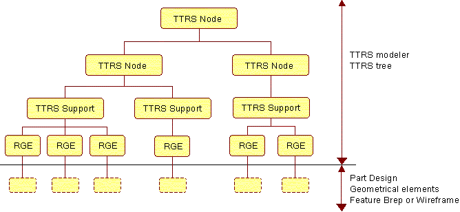
This use case is intended to help you to use Technological Product Specifications (TPS) interfaces [1]. The use case demonstrates CATITPS interface usage to retrieve the TTRSs features (Technologicaly and Topologicaly Related Surface) referenced by a 3D annotation . It also illustrates how to scan the TTRS structure with CATITTRS interfaces to retrieve the RGE (Reference Geometrical Elements). CATIRGE and CATIRGETopology interfaces are used to retrieve topological cells from the geometry. Finally, geometrical and topological evaluations are performed to create and display a grid of points with their normal on those cells.
This use case also illustrates how a command can add and manage temporary representation in the main 3D viewer.
[Top]
CAATpiAccessGeometry is a use case of the CAATPSInterfaces.edu framework that illustrates CATTPSInterfaces and MecModInterfaces framework capabilities.
[Top]
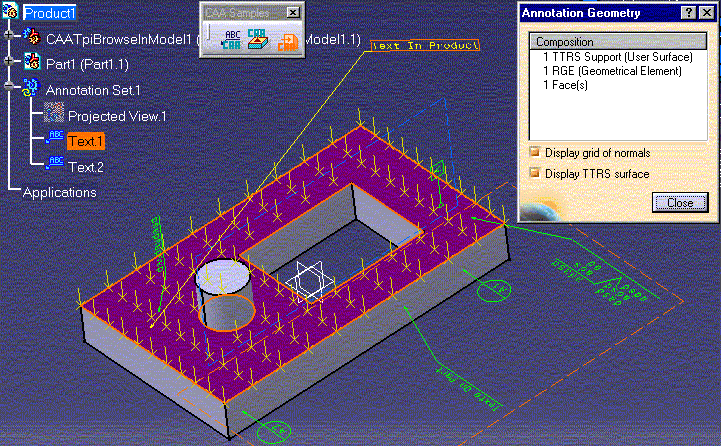
The use case is an interactive command that prompt the user to select a 3D annotation to retrieve and analyse the geometry referenced. The result of the analysis is displayed in a panel. It shows the TTRS, RGE and topological cell composition of the referenced geometry. When the topological cell is a face, a grid of point with their normals is displayed in the 3D viewer. The geometry referenced by the selected annotation is highlighted.

[Top]
The use case command is available in the toolbar "CAA Sample" of the workbench Product Functionnal & Tolerancing & Annotation.
To launch CAATpiAccessGeometry, you will need to set up the build time environment, then compile CAATPSInterfaces.edu framework along with its prerequisites, set up the run time environment, and then execute the use case [2].
Do not type the module name on the command line, but type CNEXT instead. When the application is ready, do the following:
Notice that the toolbar CAA Sample is also available in other workbenches :
[Top]
The CAATpiAccessGeometry use case is located in the CAATpiAccessGeometry.m module of the CAATPSInterfaces.edu framework:
| Windows | InstallRootDirectory\CAATPSInterfaces.edu\CAATpiAccessGeometry.m\ |
| Unix | InstallRootDirectory/CAATPSInterfaces.edu/CAATpiAccessGeometry.m/ |
where InstallRootDirectory is the directory where the CAA CD-ROM
is installed.
[Top]
There are seven logical steps in CAATpiAccessGeometry:
We will now comment each of these sections by looking at the code.
[Top]
The use case is the class CAATpiAccessGeometryCmd which is a CATStateCommand that implement the following statechart diagram.

The Buildgraph method of the command implements this statechart diagram. There are 2 agents associated to the state SelectState. SelectionAgent is a CATPathElementAgent that accept only 3D annotation, when valuated the transition method OnAnnotationSelected is called. ClosePanelAgent is a CATDialogAgent that listen the Close button of the panel to terminate the command.
[Top]
boolean CAATpiAccessGeometryCmd::OnAnnotationSelected (void * ipData)
{
if ( !_pSelectionAgent || !_pPanel ) return (TRUE);

  HRESULT rc = E_FAIL;

  int TTRSNodeCount = 0;
  int TTRSSupportCount = 0;
  int RGECount = 0;
  int FaceCount = 0;
  int EdgeCount = 0;
  int VertexCount = 0;

  // Read display parameters from panel
  _pPanel -> GetRequiredDisplay (&_bDisplay3DGrid, &_bDisplayTTRSRep);

  // Retrieve the path of the selected annotation
  CATPathElement * pPathTPS = _pSelectionAgent -> GetValue ();
  if ( pPathTPS )
  {
    // Retrieve HSO from editor and empty it
    CATFrmEditor * pEdt = GetEditor();
    if ( pEdt )
    {
      CATHSO * pHSO = pEdt -> GetHSO();
      if ( pHSO )
      {
        pHSO -> Empty();
        // Add selected PathElement in the HSO, it will be highlighted
        pHSO -> AddElements (pPathTPS);

        CATISO * pISO = pEdt -> GetISO();
        if ( pISO )
        {
          // Clean existing element in ISO
          pISO -> RemoveElement (_pModelObjectForAdditionalRep);

          // Retrieve CATITPS interface on selected 3D annotation
          CATITPS * piTPS = NULL;
          rc = pPathTPS -> Search (IID_CATITPS, (void**) &piTPS);
          if ( SUCCEEDED(rc) )
          {
            // Retrieve the list of TTRSs which are directly referenced by
            // the annotation, most often that list contains only 1 element,
            // exeptions are Semantics Targets V5 and Default Annotation
            CATITTRSList * piTTRSList = NULL;
            rc = piTPS -> GetTTRS (&piTTRSList);
            if ( SUCCEEDED(rc) )
            {
              unsigned int TTRSCount = 0;
              piTTRSList -> Count (&TTRSCount);

              CATITTRS * piTTRS = NULL;

              // Allocate representation to display surfaces of TTRSs
              // Points and normals on the TTRSs faces will be
              // added in that Rep by AnalyseTTRS method.
              CAT3DBagRep * pRep = new CAT3DBagRep();

              // Iterate on the list TTRS
              for ( unsigned int Idx = 0 ; Idx < TTRSCount ; Idx ++)
              {
                rc = piTTRSList -> Item (Idx, &piTTRS);
                if ( SUCCEEDED(rc) )
                {
                  // Analyse TTRS Composition
                  AnalyseTTRS (piTTRS, pHSO, pPathTPS,
                               TTRSNodeCount, TTRSSupportCount, RGECount,
                               FaceCount, EdgeCount, VertexCount, pRep);

                  // Construct a Rep to visualize TTRS and add it to ISO
                  AddTTRSGeometryOnRepresentation (piTTRS, pPathTPS, pRep);

                  piTTRS -> Release();
                  piTTRS = NULL;
                }
              }
              // Add new Rep in ISO
              _pModelObjectForAdditionalRep -> SetRep (pRep);

              pISO -> AddElement (_pModelObjectForAdditionalRep);
              pRep = NULL;

              piTTRSList -> Release();
              piTTRSList = NULL;
            }
            piTPS -> Release();
            piTPS = NULL;
          }
          pISO = NULL;
        }
        // No more elements to Add in the HSO, notification is send
        // and HSO content can be highlighted.
        pHSO -> EndAddElements ();
        pHSO = NULL;
      }
      pEdt = NULL;
    }
    pPathTPS = NULL;
  }
  ...
}
|
When selection agent is valuated the transition method OnAnnotationSelected is called. The CATPathElement selected pPathTPS is retrieved by calling GetValue on the selection agent. The selected 3D annotation piTPS is retrieved as a CATITPS interface pointer by using the Search method of CATPathElement . The method CATITPS::GetTTRS retrieves the list of TTRS directly referenced by the 3D annotation as a CATITTRSList interface pointer. CATITTRSList::Count and CATITTRSList::Item methods allow to iterate on the list. Each element of the list is retrieved as a CATITTRS interface pointer and provided to the method AnalyseTTRS to obtain some informations on its composition.
[Top]
HRESULT CAATpiAccessGeometryCmd::AnalyseTTRS (CATITTRS * ipiTTRS,
                                              CATHSO * ipHSO,
                                              CATPathElement * ipPathTPS,
                                              int & oTTRSNodeCount,
                                              int & oTTRSSupportCount,
                                              int & oRGECount,
                                              int & oFaceCount,
                                              int & oEdgeCount,
                                              int & oVertexCount,
                                              CAT3DBagRep * iopRep)
{
  if ( ! ipiTTRS || !ipHSO || !ipPathTPS ) return (E_FAIL);

  HRESULT oRc = E_FAIL;

  // Retrieve TTRS nature: support or node.
  CATMmrTTRSType TTRSType = ipiTTRS -> GetNature ();

  // Retrieve the components of the TTRS
  CATLISTV(CATBaseUnknown_var) CompList;
  HRESULT rc = ipiTTRS -> GetComponents (CompList);
  if ( SUCCEEDED(rc) )
  {
    int ComponentCount = CompList.Size();
    int AnalyseSuccessCount = 0;

    CATBaseUnknown_var spBaseComp;

    // If TTRS is a node, components are TTRS
    if ( TTRSType == CATMmrNodeTTRS )
    {
      oTTRSNodeCount ++; // Increment node count

      // Iterate on TTRS components and analyse them
      CATITTRS * piTTRSComp = NULL;
      for ( int i = 1 ; i <= ComponentCount ; i++ )
      {
        spBaseComp = CompList[i];
        if ( NULL_var != spBaseComp )
        {
          rc = spBaseComp -> QueryInterface(IID_CATITTRS, (void**)&piTTRSComp);
          if ( SUCCEEDED(rc) )
          {
            rc = AnalyseTTRS (piTTRSComp, ipHSO, ipPathTPS,
                              oTTRSNodeCount, oTTRSSupportCount, oRGECount,
                              oFaceCount, oEdgeCount, oVertexCount, iopRep);
            if ( SUCCEEDED(rc) )
            {
              AnalyseSuccessCount++;
            }
            piTTRSComp -> Release();
            piTTRSComp = NULL;
          }
          spBaseComp = NULL_var;
        }
      }
    }
    else // If TTRS is a support, components are RGE
    {
      oTTRSSupportCount ++; // Increment support count

      // Iterate on RGE and analyse them
      CATIRGE * piRGE = NULL;
      for ( int i = 1 ; i <= ComponentCount ; i++ )
      {
        spBaseComp = CompList[i];
        if ( NULL_var != spBaseComp )
        {
          rc = spBaseComp -> QueryInterface (IID_CATIRGE, (void**)& piRGE);
          if ( SUCCEEDED(rc) )
          {
            rc = AnalyseRGE (piRGE, ipHSO, ipPathTPS,
                             oRGECount,
                             oFaceCount, oEdgeCount, oVertexCount, iopRep);
            if ( SUCCEEDED(rc) )
            {
              AnalyseSuccessCount++;
            }
            piRGE -> Release();
            piRGE = NULL;
          }
          spBaseComp = NULL_var;
        }
      }
    }
    // method return S_OK only if each component is analysed successfuly
    if ( ComponentCount == AnalyseSuccessCount )
    {
      oRc = S_OK;
    }
  }
  return (oRc);
}
|
The AnalyseTTRS purpose is to identify the composition of the input TTRS by scanning recursively the TTRS tree downward. There are 2 kinds of TTRS : nodes and supports. For a TTRS node its components are other TTRSs, for a support TTRS its components are RGEs. CATITTRS::GetNature method allow to known if the TTRS is a node or a support. According to the nature of the input TTRS the counter oTTRSNodeCount or oTTRSSupportCount is incremented, CATITTRS::GetComponents is used to retrieved the components of a TTRS. Iteration is performed on the component list to analyse each component by calling AnalyseTTRS or AnalyseRGE method.

[Top]
HRESULT CAATpiAccessGeometryCmd::AnalyseRGE (CATIRGE * ipiRGE,
                                             CATHSO * ipHSO,
                                             CATPathElement * ipPathTPS,
                                             int & oRGECount,
                                             int & oFaceCount,
                                             int & oEdgeCount,
                                             int & oVertexCount,
                                             CAT3DBagRep * iopRep)
{
  if ( ! ipiRGE || !ipHSO || !ipPathTPS || !iopRep) return (E_FAIL);

  HRESULT oRc = E_FAIL;

  oRGECount ++; // Increment RGE Count

  CATIRGETopology * piRGETopo = NULL;
  HRESULT rc = ipiRGE -> QueryInterface (IID_CATIRGETopology,
                                         (void**)& piRGETopo);
  if ( SUCCEEDED(rc) )
  {
    CATLISTP (CATCell) * pCellList = NULL;
    rc = piRGETopo -> GetCells (&pCellList);
    if ( SUCCEEDED(rc) )
    {
      int CellCount = pCellList -> Size();
      for (int CellIdx = 1; CellIdx <= CellCount; CellIdx++)
      {
        CATCell * pCell = (*pCellList)[CellIdx];
        if ( pCell )
        {
          int CellDim = pCell -> GetDimension();
          switch ( CellDim )
          {
          case 0 : oVertexCount ++ ; break;
          case 1 : oEdgeCount ++ ; break;
          case 2 : // Cell is a Face
            {
              oFaceCount ++;
              CATFace * pFace = (CATFace*) pCell;
              CreatePointAndNormalRepresentationOnFace (pFace, piRGETopo,
                                                        ipPathTPS, iopRep);
              pFace = NULL;
            }
            break;
          }
          pCell -> Release();
          pCell = NULL;
        }
      }
      pCellList -> RemoveAll();
      delete pCellList;
      pCellList = NULL;
    }
    piRGETopo -> Release();
    piRGETopo = NULL;
  }
...
|
The AnalyseRGE method analyse the topological composition of the geometrical element referenced by the RGE. For that the interface CATIRGETopology is available on the RGE feature. The method GetCells allows to retrieve a list of topological cell. According to the dimension of each cell given by the GetDimension method the counters oVertexCount, oEdgeCount and oFaceCount are incremented. For each CATFace the method CreatePointAndNormalRepresentationOnFace is called, its behavior is described after.
[Top]
  CATIBuildPath * piBuildPath = NULL;
  rc = ipiRGE -> QueryInterface (IID_CATIBuildPath, (void**)&piBuildPath);
  if ( SUCCEEDED(rc) )
  {
    CATPathElement * pPath = NULL;
    rc = piBuildPath -> ExtractPathElement (ipPathTPS, &pPath);
    if ( SUCCEEDED(rc) )
    {
      ipHSO -> AddElements (pPath);

      SpecialTreatementForPathWithSeveralLeaf (pPath, ipHSO);

      pPath -> Release();
      pPath = NULL;
    }
    piBuildPath -> Release();
    piBuildPath = NULL;
  }
|
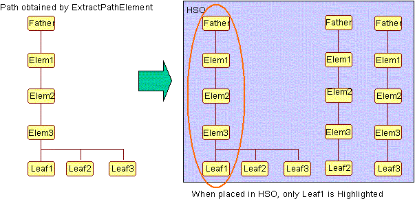
Another action performed by the AnalyseRGE method is the highlight of the referenced geometry. This is possible thank to the CATIBuildPath interface that is available on the RGE feature. The CATIBuildPath::ExtractPathElement method is used to build the CATPathElement pPath on the referenced geometry, the CATPathElement ipPathTPS of the selected TPS is used as context in ExtractPathElement. pPath is placed in the HSO by using AddElements.

In some cases the CATPathElement constructed for the referenced geometry contains several leafs. When placed in HSO only the first leaf is highlighted. To solve this problem the method SpecialTreatementForPathWithSeveralLeaf creates and adds to HSO an additionnal CATPathElement for each other leaf of the constructed CATPathElement.
[Top]
HRESULT CAATpiAccessGeometryCmd::CreatePointAndNormalRepresentationOnFace (
                                                  CATFace * ipFace,
                                                  CATIRGETopology * ipiRGETopo,
                                                  CATPathElement * ipPathTPS,
                                                  CAT3DBagRep * iopRep)
{
  if ( !ipFace || !ipiRGETopo || !ipPathTPS || !iopRep ) return (E_FAIL);

  // If display of grid is not required
  if ( !_bDisplay3DGrid ) return (S_OK);

  HRESULT oRc = E_FAIL;

  // Retrieve coefficient to direction along outside material side
  int Coefficient = 0;
  ipiRGETopo -> GetOutsideMaterialCoefficientOnNormal(&Coefficient);

  // Compute Transformation to take into account product position

  // First retrieve local transformation to apply on cells
  CATMathTransformation LocalPos;
  CATMathTransformation * pLocalPos = NULL;
  HRESULT rc = ipiRGETopo -> GetTransformation (&pLocalPos);
  if ( SUCCEEDED(rc) )
  {
    LocalPos = (*pLocalPos);

    delete pLocalPos;
    pLocalPos = NULL;
  }

  // Second retrieve transformation from product structure.
  CATMathTransformation AbsolutePos;
  CATIMovable * piMove = NULL;
  rc = ipPathTPS -> Search (IID_CATIMovable, (void**)& piMove);
  if ( SUCCEEDED(rc) )
  {
    piMove -> GetAbsPosition(AbsolutePos);

    piMove -> Release();
    piMove = NULL;
  }

  // Cumulate the two positions
  CATMathTransformation Position =  AbsolutePos * LocalPos;

  // Allocate a new rep for points and normals of that face
  CAT3DCustomRep * pPointsAndNormalsRep = new CAT3DCustomRep();

  CATSurface * pSurface = ipFace -> GetSurface();
  if ( pSurface )
  {
    const CATSurLimits * pSurLimits = ipFace -> Get2DBoundingBox();
    if ( pSurLimits && ! pSurLimits ->IsEmpty() )
    {
      double Umin = 0.0;
      double Umax = 0.0;
      double Vmin = 0.0;
      double Vmax = 0.0;
      pSurLimits -> GetExtremities(Umin, Vmin, Umax, Vmax);

      double Ucurrent = 0.0;
      double Vcurrent = 0.0;

      int GridResolution = 10;

      double FractionU = (Umax - Umin) / GridResolution;
      double FractionV = (Vmax - Vmin) / GridResolution;

      CATMathPoint PointOnSurface;
      CATMathDirection NormalAtPointOnSurface;
      CATSurParam InitialParam;
      CATMathPoint PointOnSurfacePos;
      CATMathDirection NormalAtPointOnSurfacePos;

      CATGeoFactory * pGeoFact = ipFace -> GetContainer();
      if ( pGeoFact )
      {
        // Create topological operator for checking that points are inside face
        CATPositionPtFaceOperator * pPosPtFaceOpe
         = CATCreatePositionPtFaceOperator(pGeoFact, InitialParam, ipFace);
        if ( pPosPtFaceOpe )
        {
          for ( int IdxU = 0 ; IdxU <= GridResolution ; IdxU ++)
          {
            Ucurrent = Umin + FractionU * IdxU; // Increment U parameter

            for ( int IdxV = 0 ; IdxV <= GridResolution ; IdxV ++)
            {
              Vcurrent = Vmin + FractionV * IdxV; // Increment V parameter

              // Evaluate point and normal on surface
              CATSurParam Param;
              pSurface -> CreateParam (Ucurrent, Vcurrent, Param);

              pSurface -> EvalPoint (Param, PointOnSurface);
              pSurface -> EvalNormal (Param, NormalAtPointOnSurface);

              // Check that point is inside Face Limits
              pPosPtFaceOpe -> SetSurParam (Param);
              pPosPtFaceOpe -> Run ();

              // If point is inside face limits, keep it for further treatement
              if ( CATLocationOuter != pPosPtFaceOpe-> GetOneResult() )
              {
                // Orient direction along outside material side
                if ( Coefficient != 0 )
                {
                  NormalAtPointOnSurface *= Coefficient;
                }

                // Apply Transformation to take into account product position
                PointOnSurfacePos = Position * PointOnSurface;
                NormalAtPointOnSurfacePos = Position * NormalAtPointOnSurface;

                // Create Representation of Point and normal and add it
                // to the representation
                CreateGraphicalPrimitives (pPointsAndNormalsRep, PointOnSurfacePos,
                                           NormalAtPointOnSurfacePos);
              }
            }
          }
          delete pPosPtFaceOpe;
          pPosPtFaceOpe = NULL;
        }
        pGeoFact = NULL;
      }
      pSurLimits = NULL;
    }
    pSurface = NULL;
  }
  iopRep -> AddChild((*pPointsAndNormalsRep));

  return (oRc);
}
|
The method CreatePointAndNormalRepresentationOnFace needs as input data :
The first step is to retrieve the coefficient that will be applied on the normal vectors computed on surface to orient them in the direction of the outside material of the part. This is done with CATIRGETopology::GetOutsideMaterialCoefficientOnNormal method that returns a multiplicative coefficient equal to 1 or -1. In case of problem an error value of 0 is returned.
Secondly the position matrix of the results computed from cell is calculated. The local transformation is retrieved by CATIRGETopology::GetTransformation and the global position is retrieved by calling GetAbsPosition, on the CATIMovable interface pointer retrieved on the CATPathElement of the selected annotation. The local and global transformation are cumulated to obtain the position.
[Top]
The use case finishes when the command ended by pressing the close button in the panel.
[Top]
This use case has demonstrated how to access and manipulate 3D Annotations geometry.
[Top]
| [1] | Technological Product Specification Overview |
| [2] | Building and Launching a CAA V5 Use Case |
[Top]
| History | |
| Version: 1 [Feb 2002] | Document created |
|
[Top] |
|
Copyright © 2002, Dassault Systèmes. All rights reserved.