
Machining |
Machining Algorithms |
Multi-axis Machining AlgorithmsCreating points with multi-axis machining algorithms |
| Use Case | ||
AbstractThis article discusses the CAASmaMultiAxisAlgorithms use case and explains how to use multi-axis machining algorithms. |
This use case is intended to help you run multi-axis machining algorithms. Its main intent is to explain how to set parameters, compute and read results of machining algorithms, which are:
[Top]
CAASmaMultiAxisAlgorithms is a use case of the CAASurfaceMachiningAlgoItf.edu framework that illustrates the SurfaceMachiningAlgoInterfaces framework capabilities.
[Top]
CAASmaMultiAxisAlgorithms creates geometrical points, that follow tool paths computed by multi-axis sweeping and multi-axis contour driven algorithms.
|
|
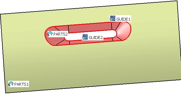
It opens a Part document, finds the first geometrical set and retrieves geometry of PARTS1, PARTS2, GUIDE1 and GUIDE2. |
|
|
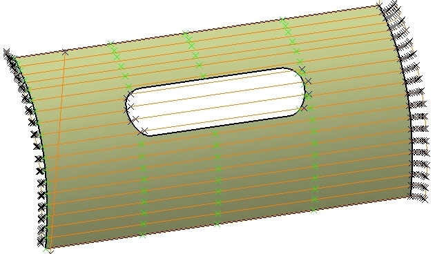
It runs a multi-axis sweeping algorithm on PARTS1 and creates a first set of points (points lying on the surface are green). |
|
|
It runs a multi-axis contour driven algorithm on PARTS2 between GUIDE1 and GUIDE2 and creates a second set of points. |
[Top]
To launch CAASmaMultiAxisAlgorithms, you will need to set up the build time environment, then compile CAASmaMultiAxisAlgorithms along with its prerequisites, set up the run time environment, and then execute the use case [1].
To launch the use case, execute the following command:
mkrun -c "CAASmaMultiAxisAlgorithms Filename"
where Filename is the path of a Part document. You can use the CAAMultiAxisAlgorithms.CATPart
located:
| Unix | InstallRootDirectory/CAASurfaceMachiningAlgoItf.edu/InputData |
| Windows | InstallRootDirectory\CAASurfaceMachiningAlgoItf.edu\InputData |
[Top]
The use case code is located in the CAASmaMultiAxisAlgorithms.m module of the CAASurfaceMachiningAlgoItf.edu framework:
| Windows | InstallRootDirectory\CAASurfaceMachiningAlgoItf.edu\CAASmaMultiAxisAlgorithms.m |
| Unix | InstallRootDirectory/CAASurfaceMachiningAlgoItf.edu/CAASmaMultiAxisAlgorithms.m |
where InstallRootDirectory is the directory where the CAA CD-ROM
is installed.
[Top]
There are five logical steps in CAASmaMultiAxisAlgorithms:
We will now comment each of those sections by looking at the code.
[Top]
First, we need to get geometries used by machining algorithms.
   CATDocument *pPartDoc = NULL;
   rc = CATDocumentServices::OpenDocument(InputPathName, pPartDoc);
   ...
   CATIPartRequest_var spPartRequest(spPart);
   if (NULL_var != spPartRequest)
   {
      CATListValCATBaseUnknown_var ListOfSurfacicSets;
      spPartRequest->GetSurfBodies(CATUnicodeString (""), ListOfSurfacicSets);
      ...
|
The CATDocumentServices::OpenDocument static method opens the part
document from the location given as first argument of the main program. From the
root container of the part, we get the CATIPartRequest interface and use
it to access to the first geometrical set of the part.
      CATIDescendants_var spDescOnSurfacicSet = ListOfSurfacicSets[1];
      if (NULL_var != spDescOnSurfacicSet)
      {
         CATListValCATISpecObject_var ListOfGeometricalElts;
         spDescOnSurfacicSet->GetDirectChildren(CATIGeometricalElement::ClassName(), ListOfGeometricalElts);
         ...
         for (int ig=1;ig<=NbGeometricalElts;ig++)
         {
            CATIGeometricalElement_var spGeomElement = ListOfGeometricalElts[ig];
            if (NULL_var != spGeomElement)
            {
               CATBody_var spBody = spGeomElement->GetBodyResult();
               ...
|
We scan its children features thanks to GetDirectChildren, and get
the topological result with GetBodyResult.
                  spBody->GetAllCells(ListOfCells,2);
                  for (int i=1;i<=NbCells;i++)
                  {
                     CATFace_var spFace = ListOfCells[i];
                     if (NULL_var != spFace)
                     {
                        if (0 != IsParts1) ListOfParts1.Append(spFace);
                        else ListOfParts2.Append(spFace);
			...
|
From features called PARTS1 and PARTS2, we get the faces and fill the according
lists ListOfParts1 and ListOfParts2.
                  spBody->GetAllCells(ListOfCells,1);
                  for (int i=1;i<=NbCells;i++)
                  {
                     CATEdge_var spEdge = ListOfCells[i];
                     if (NULL_var != spEdge)
                     {
                        CATEdgeCurve * pEdgeCurve = spEdge->GetCurve();
                        CATCurve_var spCurve = pEdgeCurve;
                        if (NULL_var != spCurve)
                        {
                           if (0 != IsGuide1) ListOfGuide1.Append(spCurve);
                           else ListOfGuide2.Append(spCurve);
                           ...
|
From features called GUIDE1 and GUIDE2, we get the curves and fill the according
lists ListOfGuide1 and ListOfGuide2.
[Top]
To store algorithms results, we need to get a machining tool path container.
   CATDocument *pProcessDoc = NULL;
   rc = CATDocumentServices::New("Process", pProcessDoc );
   ...
   CATIMfgMachiningContainer * piMfgEnvt = NULL;
   piProcessContainer->QueryInterface(CATIMfgMachiningContainer::ClassId(), (void**)&piMfgEnvt);
   if (piMfgEnvt)
   {
     piMfgEnvt->InitContainer(FALSE,0);
     ...
   }
   CATIContainer_var spTPContainer;
   CATIMfgManufacturingFactories *piFact =NULL;
   CATString ClassName("CATMfgManufacturingFactories");
   ::CATInstantiateComponent (ClassName, CATIMfgManufacturingFactories::ClassId(), (void**)& piFact);
   if (piFact)
   {
     piFact->GetManufacturingToolPathFactory(spTPContainer);
     ...
|
The CATDocumentServices::OpenDocument static method creates a process
document. From the root container of the process, we initialize the machining containers
with InitContainer and we get the tool path container thanks to the
CATIMfgManufacturingFactories interface.
[Top]
   CATIMfgMultiAxisAlgorithm *piMMSweepingAlgo =NULL;
   ::CATInstantiateComponent ("CATMfgAlgoMultiAxisSweeping", CATIMfgMultiAxisAlgorithm::ClassId(), (void**)& piMMSweepingAlgo);
   ...
   rc = piMMSweepingAlgo->SetValue(MfgAlgMachiningTolerance,0.1); // Machining tolerance
   rc = piMMSweepingAlgo->SetValue(MfgAlgMaxDiscretizationStep,100.); // Maximum discretization step
   rc = piMMSweepingAlgo->SetValue(MfgAlgMaxDistance,10.); // Distance on part

   rc = piMMSweepingAlgo->SetDirection(MfgAlgViewDirection,XVector); // View dir
   rc = piMMSweepingAlgo->SetDirection(MfgAlgStartDirection,YVector); // Start dir

   rc = piMMSweepingAlgo->SetSurfacicGeometry(MfgAlgParts,ListOfParts1); // Parts

   rc = piMMSweepingAlgo->AddMacroSyntax(1,"START"); // Approach macro
   rc = piMMSweepingAlgo->AddMacroTangentMotion(1,10.,90.,0.);
   rc = piMMSweepingAlgo->AddMacroToAPlaneMotion(1,MacroPlane);

   rc = piMMSweepingAlgo->AddMacroSyntax(2,"END"); // Retract macro
   rc = piMMSweepingAlgo->AddMacroToAPlaneMotion(2,MacroPlane);

   rc = piMMSweepingAlgo->AddMacroSyntax(3,"START"); // Linking Approach macro
   rc = piMMSweepingAlgo->AddMacroAxialMotion(3);

   rc = piMMSweepingAlgo->AddMacroSyntax(4,"END"); // Linking Retract macro
   rc = piMMSweepingAlgo->AddMacroAxialMotion(4);

   rc = piMMSweepingAlgo->AddMacroSyntax(5,"START"); // Return in a level Approach macro
   rc = piMMSweepingAlgo->AddMacroCircularMotion(5,90.,90.,10.);

   rc = piMMSweepingAlgo->AddMacroSyntax(6,"END"); // Return in a level Retract macro
   rc = piMMSweepingAlgo->AddMacroCircularMotion(6,90.,90.,10.);
   ...
   CATBaseUnknown_var spSweepingTP;
   rc = piMMSweepingAlgo->ComputeToolPath(spTPContainer,spSweepingTP);
|
First we create an instance of the multi-axis sweeping algorithm with the
CATInstantiateComponent global function, the instance name is "CATMfgAlgoMultiAxisSweeping",
we can also use MultiAxisSweepingInstanceName constant. Then we set parameters trough
the CATIMfgMultiAxisAlgorithm interface.
SetValue method is used to set the following numerical parameters:
MfgAlgMachiningTolerance: Machining tolerance, it is the maximum
allowed distance between the theoretical and computed tool pathMfgAlgMaxDiscretizationStep: Maximum discretization step, it
ensures linearity between points that are far apartMfgAlgMaxDiscretizationAngle: Maximum discretization angle,
it specifies the maximum angular change of tool axis between tool positionsMfgAlgMaxDistance: Distance on part, it defines the maximum
distance between two consecutive tool pathsMfgAlgMachiningMode: Tool path style, the cutting mode is one
way or zigzagMfgAlgStepoverSide: Stepover side, it determines the side of
the machining directionSetDirection method sets a direction:
MfgAlgViewDirection: View directionMfgAlgStartDirection: Start directionSetSurfacicGeometry method sets the geometry of the parts. The call
of this method is mandatory.
Macros motions are defined by one or several elementary motions with the following methods:
AddMacroAxialMotion: along the tool axisAddMacroTangentMotion: tangent at its end to the tool path
AddMacroRampingMotion: following a slope AddMacroCircularMotion: in a arcAddMacroToAPlaneMotion: up to a plane AddMacroAlongALineMotion: along a vector AddMacroSyntax: insert a user syntax SetTool method sets a manufacturing tool. If we don't call it, then
a default ball end tool will be used during computation.
At last, ComputeToolPath creates and returns a tool path. It is
created in the container pointed by spTPContainer.
[Top]
   CATIMfgMultiAxisAlgorithm *piMMContourDriven =NULL;
   ::CATInstantiateComponent ("CATMfgAlgoMultiAxisContourDriven", CATIMfgMultiAxisAlgorithm::ClassId(), (void**)& piMMContourDriven);
   ...
   rc = piMMContourDriven->SetValue(MfgAlgMachiningTolerance,0.1); // Machining tolerance
   rc = piMMContourDriven->SetValue(MfgAlgMaxDistance,10.); // Distance on part
   rc = piMMContourDriven->SetValue(MfgAlgOffsetOnGuide1,-1.); // Offset on guide 1
   rc = piMMContourDriven->SetValue(MfgAlgOffsetOnGuide2,-1.); // Offset on guide 2
   rc = piMMContourDriven->SetValue(MfgAlgContouringMode,1); // Between Contour guiding strategy
   rc = piMMContourDriven->SetValue(MfgAlgMachiningMode,1); // One-way tool path style

   CATMathVector NormalView(2.,0.,1.);
   rc = piMMContourDriven->SetDirection(MfgAlgViewDirection,NormalView); // View dir
   rc = piMMContourDriven->SetDirection(MfgAlgStartDirection,YVector); // Start dir

   rc = piMMContourDriven->SetSurfacicGeometry(MfgAlgParts,ListOfParts2); // Parts
   rc = piMMContourDriven->SetWireFrameGeometry(MfgAlgGuide1,ListOfGuide1); // First guide
   rc = piMMContourDriven->SetWireFrameGeometry(MfgAlgGuide2,ListOfGuide2); // Second guide

   rc = piMMContourDriven->AddMacroSyntax(1,"START"); // Approach macro
   rc = piMMContourDriven->AddMacroTangentMotion(1,10.,90.,0.);
   rc = piMMContourDriven->AddMacroToAPlaneMotion(1,MacroPlane);

   rc = piMMContourDriven->AddMacroSyntax(2,"END"); // Retract macro
   rc = piMMContourDriven->AddMacroTangentMotion(2,10.,90.,0.);
   rc = piMMContourDriven->AddMacroToAPlaneMotion(2,MacroPlane);
   ...
   CATBaseUnknown_var spContourDrivenTP;
   rc = piMMContourDriven->ComputeToolPath(spTPContainer,spContourDrivenTP);
|
First we create an instance of the multi-axis contour driven algorithm with the
CATInstantiateComponent global function, the instance name is "CATMfgAlgoMultiAxisContourDriven",
we can also use MultiAxisContourDrivenInstanceName constant. Then we set parameters trough
the CATIMfgMultiAxisAlgorithm interface.
SetValue method sets numerical parameters. All parameters of multi-axis
sweeping are available for multi-axis contour driven. Additional parameters are:
MfgAlgOffsetOnGuide1: Offset on guide 1MfgAlgOffsetOnGuide2: Offset on guide 2MfgAlgPositionOnGuide1: Position with respect to the guide
1MfgAlgPositionOnGuide2: Position with respect to the guide
2MfgAlgContouringMode: Guiding strategy, it is between contours
or parallel contourMfgAlgFromToContour: Direction in parallel contour mode, it
starts from the guide or it is done up to the guideSetSurfacicGeometry method sets the geometry of the parts. The call
of this method is mandatory.
SetWireFrameGeometry method sets one of the following geometry:
MfgAlgGuide1: First guide, it is a mandatory geometryMfgAlgGuide2: Second guide, it is a mandatory geometry in between
contours modeMfgAlgStop1: First stop , it delimits the ends of pathsMfgAlgStop2: Second stop, it delimits the ends of pathsMfgAlgLimitLine: Limiting contour, it defines a limit to the
part surface and is also available for multi-axis sweeping algorithmDirection, tool and macro motions are defined like in the multi-axis sweeping algorithm.
At last, ComputeToolPath creates and returns a tool path. It is
created in the container pointed by spTPContainer.
[Top]
Finally we scan information of tool paths and create points in the part document.
   ...
   CATIPrtContainer_var spPrtContainer = ispPartContainer;
   if (NULL_var != spPrtContainer)
   {
      CATISpecObject_var spRootPart = spPrtContainer->GetPart();
      spMechRootFactory->CreateGeometricalSet("",spRootPart,ospGeomSet);
   }
   ...
   CATIMfgTPMultipleMotion_var spMultipleMotion ((*pListOfMultipleMotion)[1]);
   if (NULL_var != spMultipleMotion)
   {
      spMultipleMotion->GetNumberOfSubTrajects(NbSubTrajects);
      for (int ia=1;ia<=NbSubTrajects;ia++)
      {
         CATIMfgTPMultipleMotion::SubTrajectType SubTrajectType;
         spMultipleMotion->GetSubTrajectType(ia,SubTrajectType);
         if (CATIMfgTPMultipleMotion::UserSyntax == SubTrajectType) // Syntax defined in macros
         {
            CATUnicodeString Syntax;
            spMultipleMotion->GetUserSyntaxCharacteristics(ia,Syntax);
            if (0 != Syntax.Compare("START")) GreenColor = 1;
            else if (0 != Syntax.Compare("END")) GreenColor = 0;
         }
         else // Traject
         {
            int StartNumber =0, EndNumber =0;
            spMultipleMotion->GetStartAndEndNumber(ia,StartNumber,EndNumber);
            for (int ib=StartNumber;ib<=EndNumber;ib++)
            {
               double x=0.,y=0.,z=0.;
               spMultipleMotion->GetTipPoint(ib,x,y,z);
               double Coord [3] = {x,y,z};
               CATIGSMPoint_var spGSMPoint = spGSMFactory->CreatePoint(Coord);
               ...
               if (1 == GreenColor) // Points lying on parts will be green
               {
                  CATIVisProperties_var spGraphicsPoint = spGSMPoint;
                  if (NULL_var != spGraphicsPoint)
                  {
                     CATVisPropertiesValues VisProperties;
                     VisProperties.SetColor(0, 255, 0); // Green color
                     spGraphicsPoint->SetPropertiesAtt(VisProperties, CATVPColor, CATVPPoint);
                     ...
|
First we create a new geometrical set in the part container with CreateGeometricalSet
method. Then we get a pointer on CATIMfgTPMultipleMotion and we scan the
tool path. For each sub-trajects, we get the type with GetSubTrajectType
and the position of tool path points with GetTipPoint.
Points are created in the new geometrical set thanks to the CreatePoint
method of CATIGSMFactory interface.
With the help of "START" and "END" user syntax defined in macros motions, we know which points
are on the part surface and we colored them in green thanks to SetPropertiesAtt
method of CATIVisProperties interface.
[Top]
[Top]
| [1] | Building and Launching a CAA V5 Use Case |
| [Top] | |
| Version: 1 [Mar 2006] | Document created |
| [Top] | |
Copyright © 2006, Dassault Systèmes. All rights reserved.