Mechanical Modeler |
Sketcher |
Creating Sketching Elements in a Part DocumentUsing sketching objects and factory to create a simple constrained sketch |
| Use Case | ||
AbstractThis article discusses the CAASkiBasicGeometries use case. This use case explains how to create a Part document, create geometry and constraints in sketch and make some operations: solving geometry and dimension systems and making corner. |
This use case is intended to show you how to :
[Top]
CAASkiBasicGeometries is a use case of the CAASketcherInterfaces.edu framework that illustrates the SketcherInterfaces framework capabilities.
[Top]
|
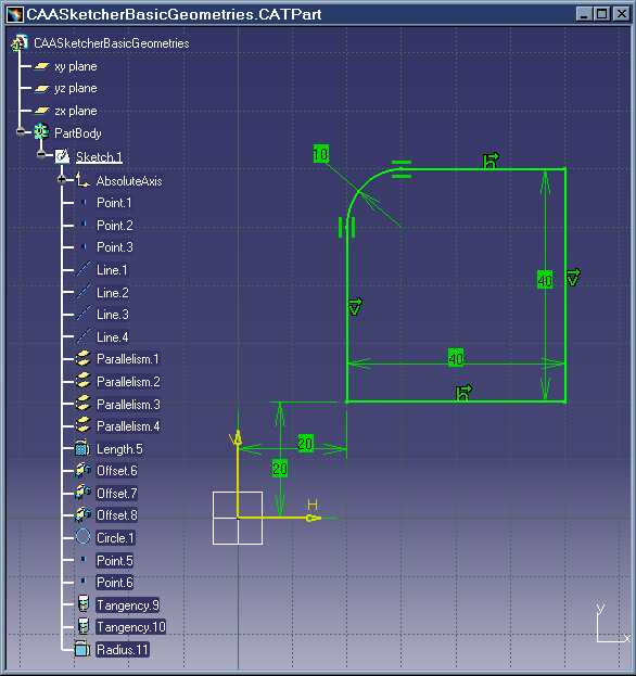
This picture represents a CATPart document created by the use case. The program creates a basic PartBody composed of one sketch. The sketch contains:
[Top]
To launch CAASkiBasicGeometries , you will need to set up the build time environment, then compile CAASkiBasicGeometries along with its prerequisites, set up the run time environment, and then execute the use case [1].
When you launch the use case, pass the full pathname of the file into which you you want to store the created document as argument: for example Result.CATPart.
e:> CAASkiBasicGeometries Result.CATPart |
$ CAASkiBasicGeometries Result.CATPart |
[Top]
The CAASkiBasicGeometries use case is made of a main program located in the CAASkiBasicGeometries.m module of the CAASketcherInterfaces.edu framework:
| Windows | InstallRootDirectory\CAASketcherInterfaces.edu\CAASkiBasicGeometries.m\ |
| Unix | InstallRootDirectory/CAASketcherInterfaces.edu/CAASkiBasicGeometries.m/ |
where InstallRootDirectory is the directory where the CAA CD-ROM
is installed.
[Top]
There are ten steps in CAASkiBasicGeometries:
[Top]
int main(int    iArgc,   // Number of arguments (1)
         char** iArgv)   // Path to the new *.CATPart document
{
  if(iArgc>2) return 1;
  char *pFileName = iArgv[1];
  char *pSessionIdent = "SampleSession";

  CATSession *pSession = NULL;
  Create_Session(pSessionIdent,pSession);
  CATDocument *pDocument = NULL;
  CATDocumentServices::New("CATPart",pDocument);
  if ( NULL == pDocument ) return 1;
  CATInit_var spInit (pDocument);
  if( NULL_var == spInit ) return 3;
  spInit->Init(TRUE);

  CATIContainerOfDocument_var spDoc = pDocument;
	CATIContainer *piContainer = NULL;
  if ( FAILED(spDoc->GetSpecContainer( piContainer)) ) return 4;
  CATIPrtContainer *piPrtContainer = NULL;
  HRESULT hr = piContainer->QueryInterface( IID_CATIPrtContainer, (void **)&piPrtContainer );
  if ( FAILED(hr) ) return 5;
  CATIPrtPart_var spPart(piPrtContainer->GetPart());
  piPrtContainer->Release();
...
|
This section represents the usual sequence for creating a Part document (CATPart).
[Top]
... CATLISTV(CATISpecObject_var) spRefPlanes = spPart->GetReferencePlanes(); //------------------------------------------------------------------------------------------ // SKETCH CREATION and EDIT:Instantiates the sketch with the plane XY (refPlanes[1]) //------------------------------------------------------------------------------------------ CATISketchFactory_var spSketchFactory(piContainer); if ( NULL_var == spSketchFactory ) return 6; CATISketch_var spSketch(spSketchFactory->CreateSketch(spRefPlanes[1])); if ( NULL_var == spSketch ) return 7; spSketch->OpenEdition(); ... |
After having retrieving the reference planes of the part, we create a sketch on the first plane (xy-plane). We make it ready for edition. The sketch is created on the sketch factory (the sketch factory interface is implementing on the container).
[Top]
...
  CATI2DWFFactory_var sketch2DFactory(spSketch); // Retrieves the 2D factory to create elements
  CATI2DPoint_var spPt_bottom_left, spPt_bottom_right, spPt_top_right, spPt_top_left;
  CATI2DLine_var spLine1, spLine2, spLine3, spLine4;
  double pt_bottom_left[2]  = {10., 10.};
  double pt_bottom_right[2] = {50., 10.};
  double pt_top_right[2]    = {50., 50.};
  double pt_top_left[2]     = {10., 50.};

  spPt_bottom_left  = sketch2DFactory->CreatePoint(pt_bottom_left);
  spPt_bottom_right = sketch2DFactory->CreatePoint(pt_bottom_right);
  spPt_top_right    = sketch2DFactory->CreatePoint(pt_top_right);
  spPt_top_left     = sketch2DFactory->CreatePoint(pt_top_left);
  spLine1 = sketch2DFactory->CreateLine(pt_bottom_left,pt_bottom_right);
  spLine2 = sketch2DFactory->CreateLine(pt_bottom_right,pt_top_right);
  spLine3 = sketch2DFactory->CreateLine(pt_top_right,pt_top_left);
  spLine4 = sketch2DFactory->CreateLine(pt_top_left,pt_bottom_left);

  // connectivity
  CATI2DCurve_var spCurve1 (spLine1);
  CATI2DCurve_var spCurve2 (spLine2);
  CATI2DCurve_var spCurve3 (spLine3);
  CATI2DCurve_var spCurve4 (spLine4);
  spCurve1->SetStartPoint(spPt_bottom_left);
  spCurve1->SetEndPoint(spPt_bottom_right);
  spCurve2->SetStartPoint(spPt_bottom_right);
  spCurve2->SetEndPoint(spPt_top_right);
  spCurve3->SetStartPoint(spPt_top_right);
  spCurve3->SetEndPoint(spPt_top_left);
  spCurve4->SetStartPoint(spPt_top_left);
  spCurve4->SetEndPoint(spPt_bottom_left);
...
|
The geometry factory is directly implemented on the sketch. After having retrieved the 2D factory, we create four points, then four lines passing by these points (these four lines make a rectangle with common points). We establish connectivity on these points. Each curve shares a starting point and end point.
[Top]
...
  CATI2DConstraintFactory_var spConstraint2DFactory(spSketch);
  spConstraint2DFactory->CreateConstraint( spLine1, NULL, NULL, NULL, NULL, NULL, NULL,
                                           Cst2DType_Horizontal, 0, 0 );
  spConstraint2DFactory->CreateConstraint( spLine2, NULL, NULL, NULL, NULL, NULL, NULL,
                                           Cst2DType_Vertical, 0, 0 );
  spConstraint2DFactory->CreateConstraint( spLine3, NULL, NULL, NULL, NULL, NULL, NULL,
                                           Cst2DType_Horizontal, 0, 0 );
  spConstraint2DFactory->CreateConstraint( spLine4, NULL, NULL, NULL, NULL, NULL, NULL,
                                           Cst2DType_Vertical, 0, 0 );
  spConstraint2DFactory->CreateConstraint( spLine2, NULL, NULL, NULL, NULL, NULL, NULL,
                                           Cst2DType_Length, 0, 0 );
  spConstraint2DFactory->CreateConstraint( spLine2, NULL, spLine4, NULL, NULL, NULL, NULL,
                                           Cst2DType_Distance, 0, 0 );
...
|
The constraint factory is directly implemented on the sketch. After having retrieved the 2D constraint factory, we create four constraints (horizontal and vertical on lines), then we create two dimensional constraints (length on a line and distance between two other lines).
[Top]
... pt_bottom_left[0] = 20.; pt_bottom_left[1] = 20.; spPt_bottom_left->SetPointData(pt_bottom_left); ... |
We change the coordinates of the first point created.
[Top]
... CATLISTV(CATI2DWFGeometry_var) spSoftReferences(1); spSoftReferences.Append(spPt_bottom_left); spSketch->Evaluate(spSoftReferences); ... |
We solve the dimensional system. The last point modified has the top
priority. Geometry evaluation with soft reference element (spPt_bottom_left),
solver tries to keep fixed these elements (spPt_bottom_left is the
more prioritary). If we do not give the first point with high priority, the last
modification (changing the first point position) would be useless. In this case
the rectangle translates totally.
[Top]
...
  CATI2DAxis_var spSupport;
  spSketch->GetAbsolute2DAxis(spSupport);
  spConstraint2DFactory->CreateConstraint( spPt_bottom_left, NULL, spSupport->GetHDirection(), NULL, NULL, NULL, NULL,
                                           Cst2DType_Distance, 0, 0 );
  spConstraint2DFactory->CreateConstraint( spPt_bottom_left, NULL, spSupport->GetVDirection(), NULL, NULL, NULL, NULL,
                                           Cst2DType_Distance, 0, 0 );
...
|
In this example the sketch is isoconstrained because the rectangle is rigid. We position it on the sketch support (and create two constraints between the first point and H-direction and V-direction). The rectangle is fixed now and it is sufficiently constrained.
[Top]
...
  double radius = 10.;
  double pt_center[2]  = {70., 40.};
  CATI2DCurve_var spCurve5 = sketch2DFactory->CreateCorner(spCurve3, spCurve4, pt_center, &radius);
  CATI2DTopologicalOperators_var spOperateur = spSketch;
  spOperateur->InsertCorner(spCurve5,spLine3,1,spLine4,1);
  spConstraint2DFactory->CreateConstraint( spLine3, NULL, spCurve5, NULL, NULL, NULL, NULL,
                                           Cst2DType_Tangent, 0, 0);
  spConstraint2DFactory->CreateConstraint( spCurve5, NULL, spLine4, NULL, NULL, NULL, NULL,
                                           Cst2DType_Tangent, 0, 0);
  spConstraint2DFactory->CreateConstraint( spCurve5, NULL, NULL, NULL, NULL, NULL, NULL,
                                           Cst2DType_Radius, 0, 1);
...
|
We create an operation on the geometry factory. This operation corresponds to
a corner between two lines of the rectangle and we specify the relimitation
(with all element trimed). We create two tangency, for creating a corner in
tangency on the lines and we create the radius of the corner. Note that the last
arguments of the CreateConstraint method is "1", because
we want to solve the dimensional system a last once.
[Top]
... spSketch->CloseEdition(); ... |
We close the sketch edition.
[Top]
... CATDocumentServices::SaveAs(*pDocument,pFileName); pSession->Delete_Session(pSessionIdent); // Memory cleaning piContainer->Release(); return 0; } |
This section represents the usual sequence for saving a document.
[Top]
This use case shows the objects and interfaces used when creating a CATPart
document, and when creating a Sketch containing 2D elements. A handler to the CATISketch
interface is the key to enter and navigate the sketcher structure, and Retrieves
the 2D factory to create elements. The 2D factory also implements the CATI2DConstraintFactory
interface to create contrainst on the elements and also solve dimension system.
[Top]
| [1] | Building and Launching a CAA V5 Use Case |
| [2] | Creating a New Document |
| [Top] | |
| Version: 1 [Feb 2000] | Document created |
| [Top] | |
Copyright © 2000, Dassault Systèmes. All rights reserved.