Equipment & Systems |
Schematics Platform Modeler |
Creating Schematic Application ComponentsWorking with Schematic Components |
| Use Case | ||
AbstractThis article discusses the CAASchAppSample1 use case. |
This use case is intended to help you understand how to use the CAA Schematic Platform Interfaces to create Schematic components.
[Top]
CAASchAppSample1 is a use case of the CAASchPlatformModeler.edu framework that illustrates CAASchPlatformModeler framework capabilities. The use case demonstrates the creation of a component for a sample Schematics application, CAASCHEDU_SamplePID.
[Top]
The sample will create a component (feature reference) with two connectors and an internal flow. An Instance of the component is then created on the main sheet of the output drawing.
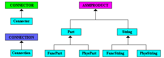
The sample uses a Schematic Extension Container to obtain the Schematics Base Factory and Application factory interfaces. It then makes a component reference object, adds connectors and internal flow to it, and instantiates (places) it on the main sheet of the drawing. The sample uses the Catalog, CAASCHEDUApp.CATfct. Here is an image of the contents of this catalog:
|
[Top]
To launch CAASchAppSample1, you will need to set up the build time environment, then compile CAASchAppSample1 along with its prerequisites, set up the run time environment, and then execute the sample. This is fully described in the referenced article [1]. When launching the use case, you must pass the following arguments:
[Top]
CAASchAppSample1 code is located in the CAASchAppSample1.m use case module of the CAASchPlatformModeler.edu framework:
| Windows | InstallRootDirectory\CAASchPlatformModeler.edu\CAASchAppSample1.m |
| Unix | InstallRootDirectory/CAASchPlatformModeler.edu/CAASchAppSample1.m |
where InstallRootDirectory is the root directory of your CAA V5
installation. It is made of a two unique source files named
CAASchAppSample1Main.cpp and CAASchAppSample1.cpp.
Additional prerequisite code is located in the CAASchAppUtilities.m and CAASchAppBase.m modules of the same framework.
[Top]
There are eight logical steps in CAASchAppSample1:
[Top]
In this use case, we open an input drawing containing one main sheet and one detail sheet. The detail sheet contains three views. The use case will create a new .CATProduct drawing for the sample application.
[Top]
The CAASchAppSample1 code is derived from the CAASchAppBaseEnv base class. The base class contains functionality common to the other CAASchApp samples. Initializing the environment involves the following methods:
CAASchAppSample1::InitEnvironment CAASchAppSample1::GetDraftingObjects CreateCATProductEnv::CreateCATProductEnv |
These methods perform the following functions:
[Top]
According to the rules of the Schematics Platform, a reference component is required before a component can be created and placed. The reference component is created by the CATISchBaseFactory interface method CreateSchComponent. This method builds the component reference object from the application reference and a list of graphical representations. It is the responsibility of the Schematics application, in this case CAASCHEDU_SamplePID, to retrieve the application reference object.
As one of the requirements of a schematics application, the application must implement the CATISchAppObjectFactory interface. This is the interface used by the application to create the application reference using the method AppCreateCompRef. In this use case, the application reference is already residing in the input document and AppCreateCompRef is used to retrieve it.
Notice the CATISchAppObjectFactory interface pointer is obtained from the CATISchSession interface which is tied to the session.
CATISchSession* piSchSession = NULL;
if ( SUCCEEDED( pSession->QueryInterface (IID_CATISchSession,(void**)&piSchSession) ) )
{
  HRESULT rc = piSchSession->GetSchObjInterface(SCHEDUApplication_Name,
                                                IID_CATISchAppObjectFactory,
                                                (void**)&_piSchAppObjFact);
  piSchSession->Release(); piSchSession = NULL;
}
|
CAASCHEDU_SamplePID implements the CATISchAppObjectFactory in the files CAAESchAppObjectFactory.cpp using methods in CAASchAppBaseServices.cpp. The important piece of code to know is listed below:
//---------------------------------------------------------------------------
//  Find an application object in a container by a specific class type
//---------------------------------------------------------------------------
CATISpecObject_var CAASchAppBaseServices::FindAppObjByClass (
   const CATUnicodeString &iUClass, const CATIContainer_var &iCont)
{
   HRESULT RC = S_OK;
   CATISpecObject_var spObjFound = NULL_var;
   CATUnicodeString ClassType;
   int MatchPos;
   CATISchAppConnectable *piSchAppCntbl = NULL;
   CATIExtendable_var spApplExtble = NULL_var;

   SEQUENCE (CATBaseUnknown_ptr) L0Obj = iCont->
      ListMembers(CATISpecObject::ClassName());

   int SizeOfL0Obj = L0Obj.length();
   CATISpecObject *piSpec;
   for (int iObj=0; iObj<SizeOfL0Obj; iObj++)
   {
     piSpec = (CATISpecObject *) L0Obj[iObj];
     if (NULL != piSpec)
     {
        if (!spObjFound)
        {
          ClassType = piSpec->GetType();
          printf ("Class Type -- %s\n", ClassType.ConvertToChar());
          MatchPos = ClassType.SearchSubString(iUClass);
          if (MatchPos >= 0)
          {
            printf ("Match found \n");
            spObjFound = piSpec;
          }
        }
        piSpec->Release();
        piSpec = NULL;
     }
   }
   return spObjFound;
}
|
[Top]
If a component is to be visualized, it needs Graphical Representation (GRR). A component may have more than one GRR, but can only display one GRR for a given instance. For this sample, the Component Reference Object to be created will have only one GRR. The GRR is the geometry shown in the first view on the detail sheet.
    CATSchListServices SchList;
    rc = SchList.CreateCATIUnknownList(&_piLUK);

    if ( SUCCEEDED(rc) )
    {
       if (_piLUK)
       {
          if (SUCCEEDED (_spDetailSpec->QueryInterface (IID_IUnknown,(void **) &_piUK)) )
          {
             _piLUK->Add(0,_piUK);  // This list will only have 1 graphical representation
          }
       }
    }
|
[Top]
According to the rules of the Schematics Platform, a component reference object is required before a component can be created and placed. The reference component is created by the CATISchBaseFactory interface method CreateSchComponent. This method builds the component reference object from the application reference and a list of graphical representations.
    //-------------------------------------------------------------------------
    //  Create schematic object
    //-------------------------------------------------------------------------
    rc = _piBaseFact->CreateSchComponent (_piUKAppRef, _piLUK, &_piSchComp);
    if (SUCCEEDED(rc) )
    {
      if ( _piSchComp)
      {
        rc = _piSchComp->QueryInterface (IID_CATISpecObject,(void **) &_piSpecSchComp);
        if (SUCCEEDED(rc))
        {
          _piSpecSchComp->SetName (SCHEDUPart_TestRef1);  // Name it.
        }
      }
    }
|
[Top]
A component such as a valve can have connectors. Some components may have multiple connectors. This sample adds two connectors to the Component Reference Object. In order to do this, the code must use the CATISchCompConnector interface method AddConnector. Once the connector is created, it must be aligned, ( i.e. horizontally, vertically, etc.) See the code for more detail.
    rc = piCompCtr->AddConnector (SCHEDUClass_Connector, piGrr, ctr1Loc, &piAppCtr1);
    if ( !SUCCEEDED(rc) || !piAppCtr1 )
    {
       cout << "CreateComponent: "
            << "Add Connector 1 Failed"
            << endl;
       return E_FAIL;
    }
    rc = piAppCtr1->QueryInterface (IID_CATISchCntrLocation,(void **) &piCtrLoc);
    if (SUCCEEDED (rc) && piCtrLoc )
    {
      piCtrLoc->SetAlignVector(NULL, vector1);
      CAASchAppDeleteBaseUnknown(piCtrLoc);
    }
|
[Top]
A component may have an internal flow. An internal flow represents a flow between pairs of connectors of a component. The sample creates an internal flow between the two connectors added to the component. To do this, the CATISchCompFlow interface must be obtained from the component reference object.
The sample uses the AddInternalFlow method of the CATISchCompFlow interface, which takes two arguments. The first argument represents a list of connector pairs, in this case only one connector pair. The second argument is a pointer to the internal flow created.
    rc = _piSchComp->QueryInterface (IID_CATISchCompFlow, (void **) &piCompFlow);
    if ( !SUCCEEDED(rc) || !piCompFlow )
    {
       cout << "CreateComponent: "
            << "QI Failed for IID_CATISchCompFlow"
            << endl;
       return E_FAIL;
    }
    CATSchListServices aList;
    aList.CreateCATIUnknownList(&pLICtrs); // Create a list of unknowns

    rc = piAppCtr1->QueryInterface (IID_IUnknown, (void **) &piUnknown);
    if (SUCCEEDED(rc) && piUnknown)
    {
      rc = pLICtrs->Add(0,piUnknown);
      CAASchAppDeleteBaseUnknown(piUnknown);
    }
    rc = piAppCtr2->QueryInterface (IID_IUnknown, (void **) &piUnknown);
    if (SUCCEEDED(rc) && piUnknown)
    {
      rc = pLICtrs->Add(1,piUnknown);
      CAASchAppDeleteBaseUnknown(piUnknown);
    }

    rc = piCompFlow->AddInternalFlow(pLICtrs, &piInternalFlow1);
    if ( !SUCCEEDED(rc) || !piInternalFlow1 )
    {
       cout << "CreateComponent: "
            << "AddInternalFlow failed"
            << endl;
       return E_FAIL;
    }
|
[Top]
The component reference can now be instantiated on the main sheet of the drawing. This is done with the CATISchComponent interface. The PlaceInSpace method is used to do this.
    double aDb6Axis[6] = {1.0,0.0,0.0,1.0,50.0,100.0};
    rc = _piSchComp->PlaceInSpace (NULL, aDb6Axis, &piSchComp);
    if (SUCCEEDED (rc))
    {
|
Note the aDb6Axis array contains the vector (1.0,0.0) representing the X axis, the vector (0.0,1.0) representing the Y axis, and the location (50.0,100). This vectors determines the orientation and location of the component on the sheet.
[Top]
This use case has demonstrated how to create a component reference object and instantiate it on the main sheet of the drawing for a sample Schematics application. Specifically, it has illustrated:
[Top]
| [1] | Building and Launching a CAA V5 Use Case |
| Version: 1 [April 2001] | Document created |
| [Top] | |
Copyright © 2000, Dassault Systèmes. All rights reserved.