This macro shows you how to create a simplified camshaft using Part Design scripting functionnalities.
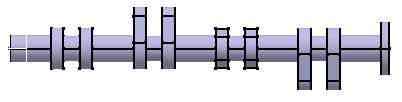
It allows you to create a camshaft for a four cylinder engine. This macro uses the Pad, Pattern, Sketch, and Constraint object capabilities.It also shows how to organize a macro with a main program, and how to create Sub that can be called several times.The simplified camshaft created is as follows:
The cam shaft is made of five bearings, four cam sets, and a driving wheel.
The bearings are made of a pad and a pattern that duplicates the pad. Each cam set is made of two identical cams separated by a pin. The cam sets are each rotated of 90 degrees about the camshaft axis. The driving wheel is a simple cylinder.
CAAPriCreateCamshaft is launched in CATIA [1]. No open document is needed.
CAAPriCamshaft.CATScript is located in the CAAscdPriUseCases module. Execute macro.
CAAPriCreateCamshaft includes six steps:
- Prolog
- Main program
- Creating the Bearings
- Creating a Cam Set
- Creating a Cam
- Creating the Pin Between two Cams and the Driving Wheel
Prolog
...
'Number Of Cylinders
' ------------------
   Dim iNumberOfCylinders As Integer

' Shaft data
' ----------
    ' -- Shaft origin
    Dim iCenterX As Integer
    Dim iCenterY As Integer

    ' -- Distance between two cams of two different cylinders
    Dim iCylinderSpacing As Integer

    ' -- Bearing diameter
    Dim iBearingDiam As Integer

    ' -- Distance between the cylinders centers
    Dim iBearingLength As Integer

    ' -- Pin diameter between two cams
    Dim iPinDiam As Integer

    ' -- Distance between 2 cams of a single cylinder
    Dim iPinLength As Integer

' Cam data
' --------
    ' -- Thickness
    Dim iCamThickness As Integer

    ' -- Circle 1 radius
    Dim iCircle1Rad As Integer

    ' -- Circle 2 radius
    Dim iCircle2Rad As Integer

    ' -- Distance between the 2 circle centers
    Dim iCircleDist As Integer

' Pi definition
' -------------
    Dim dPi As Double

' Global data to define the different elements of the camshaft
' ------------------------------------------------------------
    ' -- Cam Sketch and cam Sketch elements
    Dim oCurrentSketch  As Sketch
    Dim oCurrentLine1   As AnyObject
    Dim oCurrentLine2   As AnyObject
    Dim oCurrentCircle1 As AnyObject
    Dim oCurrentCircle2 As AnyObject

    ' -- Current distance from shaft origin
    Dim iCurrentLevel As Integer

' Part definition
' ---------------

    ' -- Part
    Dim oPart As Part

    ' -- Main tool of the part
    Dim oPartBody As Body

    ' -- Definition of YZ plane as work plane
    Dim oPlaneYZ As Reference
...
|
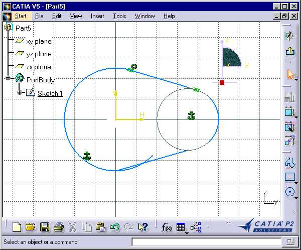
This part of the macro defines the necessary data to compute the camshaft. It contains the parameters to create the bearings, the cams, and the driving wheel, as well as objects to be reused in different Subs to avoid redeclaring them several times, and the Part main objects: the Part, the PartBody, and the YZ plane. Below are those parameters shown on a drawing of the camshaft and on the cam sketch.
The cam sketch profile is made of two circle arcs and two line segments. Constraints are set to fix the circles, to make the line segments tangent to the circles, and to make circle arc and line segment end points coincide.
Main program
...
Sub CATMain()

    ' -- Initialize global variables
    iNumberOfCylinders = 4
    iCamThickness      = 15
    iCircle1Rad        = 25
    iCircle2Rad        = 15
    iCircleDist        = 35
    iCenterY           = 0
    iCenterX           = 0
    iCylinderSpacing   = 100
    iPinDiam           = 15
    iPinLength         = 20
    iBearingDiam       = 32
    iBearingLength     = iCylinderSpacing - iPinLength - 2*iCamThickness
    dPi                = 3.14159265358979323846
    iCurrentLevel      = 0

    Dim oPartDocument As Document
    Set oPartDocument = CATIA.Documents.Add ( "Part" )
    Set oPart         = oPartDocument.Part
    Set oPartBody     = oPart.MainBody
    Set oPlaneYZ      = oPart.CreateReferenceFromGeometry( _
                                          oPart.OriginElements.PlaneYZ )

    ' -- Shading view Mode
    CATIA.ActiveWindow.ActiveViewer.RenderingMode = 1

    msgbox "Create Five Bearings"
    Call CreatePatternBearing()
    oPart.Update
    CATIA.ActiveWindow.ActiveViewer.Reframe

    msgbox "Create First Cam Set"
    Call CreateCamSet (0)
    oPart.Update
    CATIA.ActiveWindow.ActiveViewer.Reframe

    msgbox "Create Second Cam Set"
    Call CreateCamSet (90)
    oPart.Update
    CATIA.ActiveWindow.ActiveViewer.Reframe

    msgbox "Create Third Cam Set"
    Call CreateCamSet (180)
    oPart.Update
    CATIA.ActiveWindow.ActiveViewer.Reframe

    msgbox "Create Fourth Cam Set"
    Call CreateCamSet (270)
    oPart.Update
    CATIA.ActiveWindow.ActiveViewer.Reframe

    msgbox "Create Driving Wheel"
    Call CreateCylinder (iPinLength/2, iBearingDiam )
    oPart.Update
    Catia.ActiveWindow.ActiveViewer.Reframe

    msgbox "This is the macro end"

End Sub
...
|
The main program initializes the parameters (lengthes are initialized in mm), and calls different Subs:
CreatePatternBearingto create the bearings as cylinders that join the cam sets and the driving wheel- Four times
CreateCamSetto create each cam set using a different angle value (0, 90, 180, and 270 degrees.) A set of cam is made of two cams and the pin that joins the two cams.CreateCamSetcalls other Subs in turn CreateCylinderto create the driving wheel. It is also called byCreateCamSetto create the pin
The main program prompts you the task it will do before doing it using the msgbox function, and when its done, updates the part to compute the resulting geometry, and reframes the display before prompting you the next task.
Among the parameters, note iCurrentLevel that is used
throughout the macro to record the current abscissa along the camshaft
axis.
Creating the Bearings
...
Sub CreatePatternBearing()

  ' Cylinder definition: Pad from a circular sketch
  ' -----------------------------------------------

    ' -- The YZ plane is the sketch plane
    Set oCurrentSketch = oPartBody.Sketches.Add ( oPlaneYZ )

    ' -- The sketch is a circle centered on the shaft origin
    ' --  and of iBearingDiam diameter
    Dim oFactory2D as Factory2D
    Set oFactory2D = oCurrentSketch.OpenEdition
    Set oCurrentCircle1 = oFactory2D.CreateClosedCircle ( iCenterX, _
                                                          iCenterY, _
                                                          iBearingDiam/2 )
    oCurrentSketch.CloseEdition

    ' Creation of the cylindrical pad
    Dim oPad As Pad
    Set oPad = oPart.ShapeFactory.AddNewPad ( oCurrentSketch,  iBearingLength )

...
|
The pad to be patterned is a cylinder defined using a sketch that is
first added to the sketch collection as an empty object. Then it is edited
using the 2D factory object held by the sketch object between the calls to
the OpenEdition and CloseEdition methods. The
sketch is made up of a circle of the YZ plane whose center is the plane
origin, and whose radius is iBearingDiam/2, thanks to the CreateClosedCircle
method of the 2D factory object. The sketch is then used to create the pad
using the AddNewPad method of the shape factory object
available from the part object itself.
...
  ' Creating the pattern
  ' --------------------

    Dim originElements1 As OriginElements
    Set originElements1 = oPart.OriginElements

    Dim oRefPlaneXY As Reference
    Set oRefPlaneXY = oPart.CreateReferenceFromGeometry( _
                                                   oPart.OriginElements.PlaneXY )

    Dim rectPattern1 As RectPattern
    Set rectPattern1 = oPart.ShapeFactory.AddNewRectPattern(oPad,                 _
                                                            iNumberOfCylinders+1, _
                                                            1,                    _
                                                            iCylinderSpacing,     _
                                                            0.0,                  _
                                                            1,                    _
                                                            1,                    _
                                                            oRefPlaneXY,          _
                                                            oRefPlaneXY,          _
                                                            True,                 _
                                                            True,                 _
                                                            0.0)

    ' -- Update of the current level
    iCurrentLevel =  iBearingLength

End Sub
...
|
Once the pad is created, it can be patterned using a rectangular
pattern created thanks to the AddNewRectPattern method of the
shape factory object. The pattern parameters are:
oPad: The feature to be patternediNumberOfCylinders+1and1: The numbers of instances along the pattern's first and second directions respectively, that is here 5 and 1iCylinderSpacingand0.0: The spacing between each instance along the first and second directions respectively. Since there is only one instance of the pad in the second direciton, the spacing is set to 01and1: The position of the initial pad among those resulting from the pattern along the two directions respectivelyoRefPlaneXYandoRefPlaneXY: The pattern's first and second directions respectively. Referring two times to the XY plane means that the first direction is the X axis, and that the second direction is the Y axis. To enable for this, the place must be passed as a reference object. This is why theCreateReferenceFromGeometryis used from the XY plane geometric object of theOriginElementsobjectTrueandTrue: The flags that indicate whether the above direction orientations should be kept as is or inverted0.0is the angle to apply to both directions before patterning. This angle is expressed in degrees.
Finally, the abscissa of the top of the pad is put into iCurrentLevel
to be used as reference: the next pad will be created on top of it.
Creating a Cam Set
...
Sub CreateCamSet(angle)

    ' -- Create the first cam
    CreateCam(angle)
    iCurrentLevel = iCurrentLevel + iCamThickness

    ' -- Create a cylinder for the pin between cams
    Call CreateCylinder(iPinLength, iPinDiam)

    ' -- Create the second cam
    CreateCam(angle)

    ' -- Update the current level
    iCurrentLevel = iCurrentLevel + iCamThickness + iBearingLength

End Sub
...
|
CreateCamSet creates the camset according to its angle
about the shaft. It calls CreateCam, CreateCylinder,
and CreateCam again to create the first cam, the pin between
the two cams of the set, and the second cam respectively. iCurrentLevel
is updated after the two calls to CreateCam to correctly
position the next object. CreateCylinder updates it itself.
Creating a Cam
...
Sub CreateCam(angle)

    Dim dRad As Double
    dRad = angle*dPi/180

    Dim dDSin1 as Double
    dDSin1 = iCircle1Rad*sin(dRad)

    Dim dDCos1 as Double
    dDCos1 = iCircle1Rad*cos(dRad)

    Dim dDSin2 as Double
    dDSin2 = iCircle2Rad*sin(dRad)

    Dim dDCos2 as Double
    dDCos2 = iCircle2Rad*cos(dRad)

    Dim dCSin  as Double
    dCSin  = iCircleDist*sin(dRad)

    Dim dCCos  as Double
    dCCos  = iCircleDist*cos(dRad)
...
|
This first code section converts the angle passed as
argument from degrees to radians in dRad, and creates some
variables that will be used to compute the coordinates of the circle arc
and line segment end points. These end points are not intended to exactly
create the cam profile, but to give an outline. Then the circle arcs and
line segments will be constrained to create the actual cam profile. Let's
see the geometric objects' creation
...
  ' Create a sketch
  ' ---------------
    Set oCurrentSketch = oPartBody.Sketches.Add ( oPlaneYZ )

  ' Create geometric elements in the sketch
  ' ---------------------------------------
    Dim oFactory2D As Factory2D
    Set oFactory2D = oCurrentSketch.OpenEdition

    Set oCurrentLine1   = oFactory2D.CreateLine   ( _
                     iCenterX - dDSin1,          iCenterY + dDCos1, _
                     iCenterX + dCCos - dDSin2,  iCenterY + dCSin + dDCos2 )

    Set oCurrentLine2   = oFactory2D.CreateLine   ( _
                     iCenterX + dDSin1,          iCenterY - dDCos1, _
                     iCenterX + dCCos + dDSin2,  iCenterY + dCSin - dDCos2 )
...
|
The sketch is created and added to the sketch collection of the part
body using the Add method that designates the YZ plane as the
sketch plane. The sketch is then opened for edition thanks to its OpenEdition
method that returns the 2D object factory.
The first line segment is then created using the CreateLine
method of the 2D object factory. The first two arguments are the abscissa
and ordinate of the line segment start point expressed in the sketch plane
coordinate system, and the last two are those of its end point. These
coordinate values are generic and apply to any angle value. The second
line segment is created in the same way.
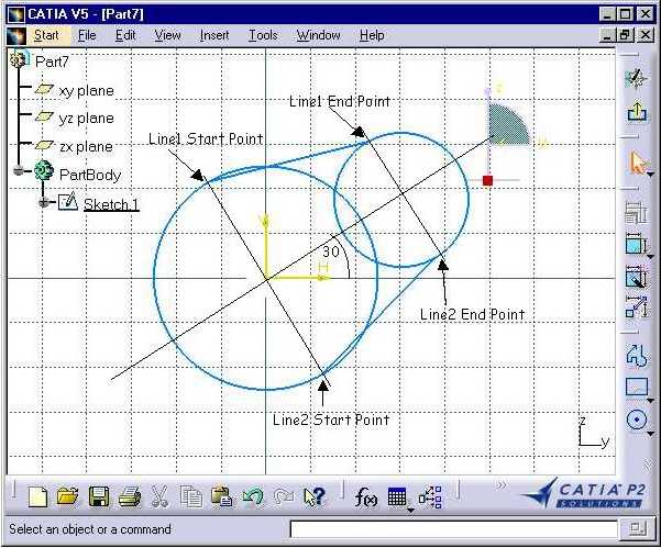
This sketch shows how the lines are created using these coordinates, for an angle of 30 degrees. Their points are located on the circles where perpendicular diameters to the circle center direction cross the circles. The circles shown here are the support circles or the circle arcs.
...
    Dim dRad1 As Double
    dRad1 = dRad - dPi/4

    Dim dRad2 As Double
    dRad2 = dRad + dPi/4

    Set oCurrentCircle1 = oFactory2D.CreateCircle ( _
                     iCenterX,                   iCenterY, _
                     iCircle1Rad,   dRad2,    dRad1)

    Set oCurrentCircle2 = oFactory2D.CreateCircle ( _
                     iCenterX + dCCos,           iCenterY + dCSin, _
                     iCircle2Rad,   dRad1,    dRad2)
...
|
Two angles, dRad1 and dRad2, are then
computed from dRad by adding and subtracting 90 degrees
(PI/4) to be used as start and end angles for the circle arcs. The first
circle arc is created using the CreateCircle method of the 2D
object factory. The first two arguments are the abscissa and ordinate of
the circle center expressed in the sketch plane coordinate system, the
third one is the circle radius, and the last two are the start angle and
end angle respectively, expressed in radians, that define the start point
and the end point of the circle arc. The second circle arc is created in
the same way. The actual geometric objects created for an angle of 0
degrees are as follows.
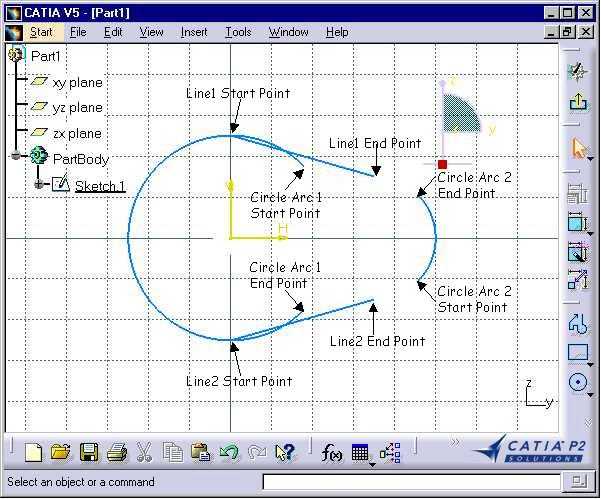
As you can see, the sketch is not closed. Constraints will then be set to these objects. But first, Reference objects must be retrieved from the geometric objects, since constraints can apply only to these Reference objects.
...
  ' Get references from elements to constraint
  ' ------------------------------------------

    Dim oRefLine1 As Reference
    Set oRefLine1 = oPart.CreateReferenceFromObject(oCurrentLine1)

    Dim oRefCircle1 As Reference
    Set oRefCircle1 = oPart.CreateReferenceFromObject(oCurrentCircle1)

    Dim oRefLine2 As Reference
    Set oRefLine2 = oPart.CreateReferenceFromObject(oCurrentLine2)

    Dim oRefCircle2 As Reference
    Set oRefCircle2 = oPart.CreateReferenceFromObject(oCurrentCircle2)

    Dim oRefLine1StartPt As Reference
    Set oRefLine1StartPt = oPart.CreateReferenceFromObject(oCurrentLine1.StartPoint)

    Dim oRefLine1EndPt As Reference
    Set oRefLine1EndPt = oPart.CreateReferenceFromObject(oCurrentLine1.EndPoint)

    Dim oRefLine2StartPt As Reference
    Set oRefLine2StartPt = oPart.CreateReferenceFromObject(oCurrentLine2.StartPoint)

    Dim oRefLine2EndPt As Reference
    Set oRefLine2EndPt = oPart.CreateReferenceFromObject(oCurrentLine2.EndPoint)

    Dim oRefCircle1StartPt As Reference
    Set oRefCircle1StartPt = _
        oPart.CreateReferenceFromObject(oCurrentCircle1.StartPoint)

    Dim oRefCircle1EndPt As Reference
    Set oRefCircle1EndPt = oPart.CreateReferenceFromObject(oCurrentCircle1.EndPoint)

    Dim oRefCircle2StartPt As Reference
    Set oRefCircle2StartPt = _
        oPart.CreateReferenceFromObject(oCurrentCircle2.StartPoint)

    Dim oRefCircle2EndPt As Reference
    Set oRefCircle2EndPt = oPart.CreateReferenceFromObject(oCurrentCircle2.EndPoint)
...
|
A Reference object is obtained for the two line segments, the two circle arcs, and for each of their end points. Now the constraints can be set.
...
  ' Create constraints
  ' ------------------
    Dim oConstraints As Constraints
    Set oConstraints = oCurrentSketch.Constraints
    Dim oConstraint As Constraint

    ' -- Fix Circle1
    Set oConstraint = oConstraints.AddMonoEltCst(catCstTypeReference, oRefCircle1)

    ' -- Fix Circle2
    Set oConstraint = oConstraints.AddMonoEltCst(catCstTypeReference, oRefCircle2)

...
|
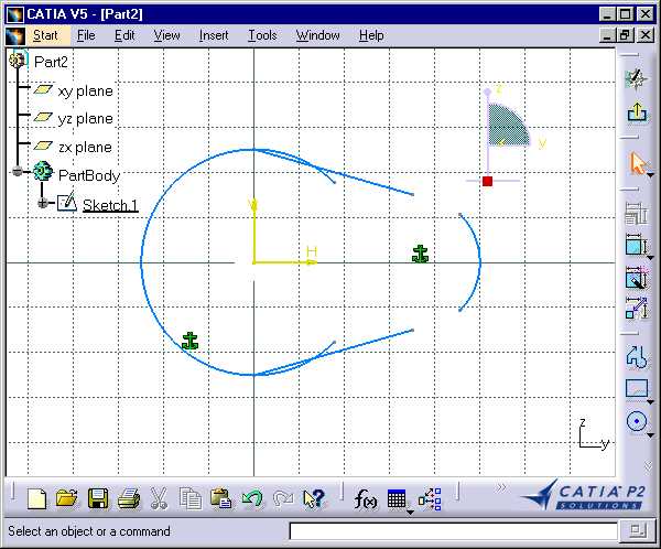
The constraint collection is retrieved from the sketch, and a current
constraint object is created to be used throughout the constraint creation
step. First, the two support circles of the two circle arcs are set as non
modifiable using a fix constraint, that is they can't move, or their
radius can't change, thanks to the AddMonoEltCst method to
which the catCstTypeReference constraint type, for fix
constraint, is passed, along with the reference to the circle. This is
shown by the tangency symbol.
...
' -- Tangency Line1 Circle1
    Set oConstraint = oConstraints.AddBiEltCst(catCstTypeTangency, _
                                               oRefLine1,          _
                                               oRefCircle1)
...
|
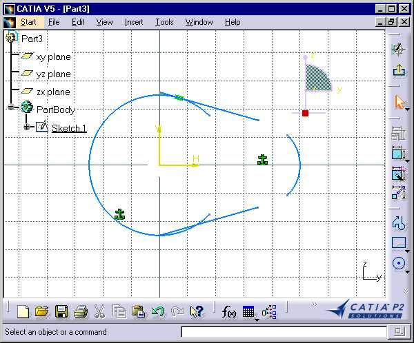
A tangency constraint is set between the first line segment and the
first circle arc, thanks to the AddBiEltCst method to which
the catCstTypeTangency constraint type, for tangency
constraint, is passed, along with the references to the line segment and
the circle arc. This is shown by the tangency symbol.
...
' -- Tangency Line1 Circle2
    Set oConstraint = oConstraints.AddBiEltCst(catCstTypeTangency, _
                                               oRefCircle2,        _
                                               oRefLine1)
...
|
Another tangency constraint is set between the first line segment and the second circle arc.
...
' -- Coincidence Circle1 Start Point Line1 Start Point
    Set oConstraint = oConstraints.AddBiEltCst(catCstTypeOn,       _
                                               oRefCircle1StartPt, _
                                               oRefLine1StartPt)
...
|
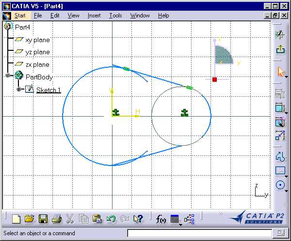
A coincidence constraint is set between the first line segment and the
first circle arc, thanks to the AddBiEltCst method to which
the catCstTypeOn constraint type, for coincidence constraint,
is passed, along with the references to the line segment and the circle
arc. This is shown by the coincidence symbol. Now the geomentric object
are relimited.
...
' -- Coincidence Circle2 End Point Line1 End Point
    Set oConstraint = oConstraints.AddBiEltCst(catCstTypeOn,     _
                                               oRefCircle2EndPt, _
                                               oRefLine1EndPt)
...
|
Another coincidence constraint is set between the first line segment and the second circle arc.

The first line segment now connects and is tangent to the two circle arcs. The same applies to the second one
...
' -- Tangency Line2 Circle1
    Set oConstraint = oConstraints.AddBiEltCst(catCstTypeTangency, _
                                               oRefLine2,          _
                                               oRefCircle1)

    ' -- Tangency Line2 Circle2
    Set oConstraint = oConstraints.AddBiEltCst(catCstTypeTangency, _
                                               oRefLine2,          _
                                               oRefCircle2)

    ' -- Coincidence Circle1 End Point Line2 Start Point
    Set oConstraint = oConstraints.AddBiEltCst(catCstTypeOn,     _
                                               oRefCircle1EndPt, _
                                               oRefLine2StartPt)

    ' -- Coincidence Circle2 Start Point Line2 End Point
    Set oConstraint = oConstraints.AddBiEltCst(catCstTypeOn,       _
                                               oRefCircle2StartPt, _
                                               oRefLine2EndPt)

    oCurrentSketch.CloseEdition

  ' Create the Pad from the sketch
  ' ------------------------------
    Dim oPad As Pad
    Set oPad = oPart.ShapeFactory.AddNewPad ( oCurrentSketch, _
                                              iCamThickness + iCurrentLevel )
    oPad.SecondLimit.Dimension.Value = iCurrentLevel*-1

End Sub
...
|
When the constraints are set, the sketch edition is closed, and the pad relying on this sketch can be created using the AddNewPad method.
Creating the Pin Between two Cams and the Driving Wheel
They are all made up of a simple cylinder created using the CreateCylinder
Sub to which the thickness, that is, the height of the cylinder, and its
radius, are passed as arguments.
...
Sub CreateCylinder(thickness, radius)

    ' -- Create a sketch
    Set oCurrentSketch = oPartBody.Sketches.Add ( oPlaneYZ )

    ' -- Create base circle in the sketch
    Dim oFactory2D As Factory2D
    Set oFactory2D = oCurrentSketch.OpenEdition
    Set oCurrentCircle1 = oFactory2D.CreateClosedCircle (iCenterX, iCenterY, radius)
    oCurrentSketch.CloseEdition

    ' -- Create the Pad from the sketch
    Dim oPad As Pad
    Set oPad = oPart.ShapeFactory.AddNewPad ( oCurrentSketch, _
                                              iCurrentLevel + thickness )
    oPad.SecondLimit.Dimension.Value = iCurrentLevel*-1

    ' -- Increase Level
    iCurrentLevel = iCurrentLevel + thickness

End Sub
...
|
A sketch is added to the sketch collection of the the part body, and
the 2D factory is retrieved by opening the sketch edition. A closed circle
is created thanks to the CreateClosedCircle method using the
radius passed as argument and whose center is the YZ plane coordinate
system origin. Then the sketch edition is closed, and the pad is created
using the AddNewPad method of the shape factory object
aggregated to the part object. It uses the just created sketch, and sets
the pad height to current level plus the thickness. At this moment, the
created pad extends from the YZ plane to the iCurrentLevel +
thickness abscissa. This is far too much. The SecondLimit
property of the pad object enables the pad to be resized. The value of the
dimension object of this second limit is set to the opposite to the
current level. The second limit value is counted positive along the
negative abscissa of the pad extrusion axis. This is why the opposite of
the current level is taken into account. This makes the pad's second face,
that is, the second one parallel to the sketch, with the top face of the
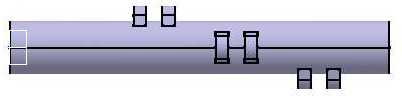
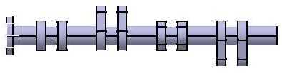
previous one, that is, the face of the last bearing. Below are two screen
shots that show the effect of these two successive pad creation
instructions.
Another way of coding could be:
...
    Dim oPad As Pad
    Set oPad = oPart.ShapeFactory.AddNewPad ( oCurrentSketch,  thickness )
    oPad.FirstLimit.Dimension.Value  = iCurrentLevel + thickness
    oPad.SecondLimit.Dimension.Value = iCurrentLevel*-1
...
|
This is a more natural way to create the pad using its actual thickness, but requests three instructions instead of two. Though the pad is created using its actual thickness, it extends from the YZ plane to the point of thickness abscissa. Its first limit, then its second limit are set. Below are three screen shots that show the effect of these three successive pad creation instructions.
![]()