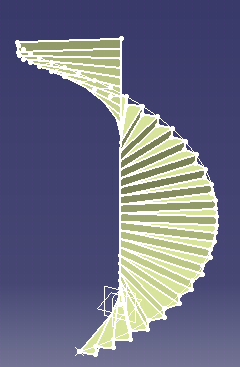
This macro shows how to use Knowledge parameters and Generative Shape Design to create repetitive geometry in a CATIA Macro:
The macro illustrates the following topics:
- Creating a CATIA Part document.
- Show/Noshow of wireframe and surfacic objects.
- Adding a new OpenBody.
- Creating parameters and formulas / Using them in wireframe and surface object definitions.
- Generating reference for each input object / CATIA methods require references as input for object creations.
- Creating wireframe and shape design objects.
- Updating CATIA Part/ Note: it has to be done at the end for better performances when replaying macro.
- Reframing the 3D window.
CAAGsiCreateStair is launched in CATIA [1]. Open a CATIA Part Document.
CAAGsiCreateStair.CATScript is located in the CAAScdGsiUseCases module. Execute macro (Windows only).
CAAGsiCreateStair includes four steps
- Creating a Part Document
- Settting Variables and Knowledge Parameters
- Computing the Number of Steps for the Stair
- Generating the Steps
- Updating the Part Document and Reframing
Creating a Part Document
  ' Creating  a Part Document
    Dim PartDoc As Document
    Set PartDoc = CATIA.Documents.Add  ( "Part" )
|
Setting Variables and Knowledge Parameters
  ' Setting knowledge parameters
    Dim parameters As Object
    Set parameters = PartDoc.Part.parameters
  ' declare of a working Parm object
    Dim Parm As Object

  ' Setting knowledge relations
    Dim relations As Object
    Set relations = PartDoc.Part.relations
  ' declare a working Formula object
    Dim Formula As Object
|
The "Parm" and "Formula" objects are collections of knowledge parameters and Formula.
 ' Creating Parameters for stair generation
    Set Parm = parameters.CreateDimension("HelixPitch", "LENGTH", Pitch)
    Set Parm = parameters.CreateDimension("HelixHeight", "LENGTH", Height)
    Set Parm = parameters.CreateDimension("StepHeight", "LENGTH", StepValue)
|
The definition of knowledge parameters and their use in creating objects allows
to parameterize object creation.
That is a key point in using CATIA V5 objects.
For example, if the "StepHeight" is not correct in the resulting CATIA Part ,
it can be interactively modified
and all the objects using "StepHeight" value are automatically updated.
   ' Creating a line for helix definition
    Dim Line As Object
    Set Line = PartDoc.Part.HybridShapeFactory.AddNewLinePtDir(Point1, Dir, 0, HelixHeight, False)
    myHBody.AppendHybridShape Line

  ' Create a formula defining the line offset value as equal to the helix height parameter
    Set Formula = relations.CreateFormula("Formula.0", "", Line.EndOffset, "HelixHeight")
  ' Set Parameters for stair generation
    Set Parm = parameters.CreateDimension("HelixPitch", "LENGTH", Pitch)
    Set Parm = parameters.CreateDimension("HelixHeight", "LENGTH", Height)
    Set Parm = parameters.CreateDimension("StepHeight", "LENGTH", StepValue)
|
The defined parameters can be used to create a formula.
For example, a formula can be associated with the Line object parameter in order to be updated if the "HelixHeight" paramater is modified
Computing the Number of Steps for the Stair
  ' Computing the number of steps to be generated
    Dim index As Integer
    index  = HelixHeight / StepHeight
    ...
  ' --------------------------------------------------------------
  ' Loop on steps
  ' --------------------------------------------------------------
  '
    Dim CounterStep As Integer
    For CounterStep = 1 To index  Step 1
      ...
    Next
|
The number of steps is directly related to the helix height and the step height. The number of step and then of the objects created in the CATIA Part Document depend on these two parameters
Generating the Steps
      ' Create a new openbody for each step
        Set myHBody = PartDoc.Part.HybridBodies.Add()

        Dim stepbody As Object
     	Set stepbody = PartDoc.Part.CreateReferenceFromObject(myHBody)
	PartDoc.Part.HybridShapeFactory.ChangeFeatureName stepbody, "Step." & CounterStep
|
Each geometry related to one step is inserted in a specific OpenBody
        'Point0 = Point reference for the step on the axis
               Dim Intersection1 As Object
               Set Intersection1 = PartDoc.Part.HybridShapeFactory.AddNewIntersection(RefLine, RefPlane)
        myHBody.AppendHybridShape Intersection1
               Set Pt0 = PartDoc.Part.CreateReferenceFromObject(Intersection1)
        PartDoc.Part.HybridShapeFactory.GSMVisibility Pt0, 0

        'Point1 = Point reference for the step on the helix
               Dim Intersection2 As Object
               Set Intersection2 = PartDoc.Part.HybridShapeFactory.AddNewIntersection(RefPlane, RefHelix)
        myHBody.AppendHybridShape Intersection2
               Set Pt1 = PartDoc.Part.CreateReferenceFromObject(Intersection2)
        PartDoc.Part.HybridShapeFactory.GSMVisibility Pt1, 0

        'PlanOffset= Step height reference plane
               Dim PlaneOffset2 As Object
               Set PlaneOffset2 = PartDoc.Part.HybridShapeFactory.AddNewPlaneOffset(RefPlane, StepHeight, False)
        myHBody.AppendHybridShape PlaneOffset2
               Set Formula = relations.CreateFormula("Formula.Step.1", "", PlaneOffset2.Offset, "StepHeight")
               Set RefPlaneOffset = PartDoc.Part.CreateReferenceFromObject(PlaneOffset2)
        PartDoc.Part.HybridShapeFactory.GSMVisibility RefPlaneOffset, 0
|
The "RefPlane" is the reference plane for each step.
A formula is associated with the offset value of the "PlaneOffset" from the
"RefPlane". Then, the "StepHeight" parameter pilots
the object creation and will update the offsetted plane position if its value
is modified afterwards.
        'Point3 = Point reference on helix
        Dim Intersection3 As Object
        Set Intersection3 = PartDoc.Part.HybridShapeFactory.AddNewIntersection(RefPlaneOffset, RefHelix)
        myHBody.AppendHybridShape Intersection3
        Set Pt3 = PartDoc.Part.CreateReferenceFromObject(Intersection3)
        PartDoc.Part.HybridShapeFactory.GSMVisibility Pt3, 0

        'Point2 = Point Projected from helix on step ground plane
        Dim Project1  As Object
        Set Project1 = PartDoc.Part.HybridShapeFactory.AddNewProject(Pt3, RefPlane)
        Project1.SolutionType = 0
        Project1.Normal = True
        myHBody.AppendHybridShape Project1
        Set Pt2 = PartDoc.Part.CreateReferenceFromObject(Project1)
        PartDoc.Part.HybridShapeFactory.GSMVisibility Pt2, 0

        ' Step definition contours : 2 lines and a circle arc
        ' Line1
        Set LinePt0Pt1 = PartDoc.Part.HybridShapeFactory.AddNewLinePtPt(Pt0, Pt1)
        myHBody.AppendHybridShape LinePt0Pt1
        Dim RefLinePt0Pt1 As Object
        Set RefLinePt0Pt1 = PartDoc.Part.CreateReferenceFromObject(LinePt0Pt1)
        PartDoc.Part.HybridShapeFactory.GSMVisibility RefLinePt0Pt1, 0

        ' Line2
        Set LinePt0Pt2 = PartDoc.Part.HybridShapeFactory.AddNewLinePtPt(Pt0, Pt2)
        myHBody.AppendHybridShape LinePt0Pt2
        Dim RefLinePt0Pt2 As Object
        Set RefLinePt0Pt2 = PartDoc.Part.CreateReferenceFromObject(LinePt0Pt2)

        ' Circle arc
        Dim Circle3Points As Object
        Set Circle3Points = PartDoc.Part.HybridShapeFactory.AddNewCircle3Points(Pt0, Pt1, Pt2)
        Circle3Points.SetLimitation 2
        myHBody.AppendHybridShape Circle3Points
        Dim RefCircle As Object
        Set RefCircle = PartDoc.Part.CreateReferenceFromObject(Circle3Points)

        Dim Split As Object
        Set Split = PartDoc.Part.HybridShapeFactory.AddNewHybridSplit(RefCircle, RefLinePt0Pt1, 1)
        PartDoc.Part.HybridShapeFactory.GSMVisibility RefLinePt0Pt1, 0
        PartDoc.Part.HybridShapeFactory.GSMVisibility RefLinePt0Pt2, 0
        PartDoc.Part.HybridShapeFactory.GSMVisibility RefCircle, 0
        myHBody.AppendHybridShape Split
        Dim RefSplit As Object
        Set RefSplit = PartDoc.Part.CreateReferenceFromObject(Split)

        ' Step surface
        Dim Fill As Object
        Set Fill = PartDoc.Part.HybridShapeFactory.AddNewFill()
        Fill.AddBound(RefLinePt0Pt1)
        Fill.AddBound(RefSplit)
        Fill.AddBound(RefLinePt0Pt2)
        myHBody.AppendHybridShape Fill

        'Riser (Opposite-step) surface
        Dim Extrude As Object
        Set Extrude = PartDoc.Part.HybridShapeFactory.AddNewExtrude(RefLinePt0Pt2, HauteurMarche, 0, Dir)
        myHBody.AppendHybridShape Extrude
        Set Formula = relations.CreateFormula("Formula.Step.2", "", Extrude.BeginOffset, "StepHeight")

        ' Join of two surfaces
        Set RefFill = PartDoc.Part.CreateReferenceFromObject(Fill)
        Set RefExtrude = PartDoc.Part.CreateReferenceFromObject(Extrude)

        Dim Join As Object
        Set Join = PartDoc.Part.HybridShapeFactory.AddNewJoin(RefFill, RefExtrude)
        PartDoc.Part.HybridShapeFactory.GSMVisibility RefFill, 0
        PartDoc.Part.HybridShapeFactory.GSMVisibility RefExtrude, 0
        myHBody.AppendHybridShape Join
|
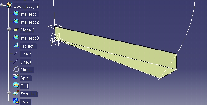
All the objects necessary to create one step are generated
Note :The wireframe and shape design objects can be put in no-show using the specific method of HybridShapeFactory: GSMVisibility
        ' End of loop - re-initializing the reference plane for the next step
        ' RefPlane = RefPlaneOffset
               Set RefPlane = PartDoc.Part.CreateReferenceFromObject(PlaneOffset2)
|
For the next loop, the "RefPlane" is updated.
The new "RefPlane" for the next step is the OffsetPane used in current step
Updating the Part Document and Reframing
     'Updating CATIA Part Document
    ' Note : Performed only at the end of geometry generation

    PtDoc.Part.Update
|
Note: The update of the CATIA Part Document is done at the end for
performances reason:
The generation of the geometry representation of the objects and their
visualization is done in one step
         ' Reframing CATIA Part Window
       Dim specsAndGeomWindow1 As Window
       Set specsAndGeomWindow1 = CATIA.ActiveWindow

       Dim viewer3D1 As Viewer
       Set viewer3D1 = specsAndGeomWindow1.ActiveViewer
    viewer3D1.Reframe

       Dim viewpoint3D1 As Viewpoint3D
|
The reframing is done to view in the 3D window all objects created and updated once the macro has been replayed