Mechanical Modeler |
Mechanical Modeler Novelties - PresentationV5R13 & V5R14 novelties |
|
| Technical Article | ||
AbstractSince V5R13, Mechanical Modeler has introduced novelties which can imply modifications in your existing code, or can have consequences on the way to lead up your new developments. The article has been cut in two parts, the current one presents the novelties, and the second one exposes the consequences in term of code [1]. This article requires Mechanical Modeler knowledge. However to help the reader, along the paragraphs, technical articles explaining Mechanical Modeler concepts or vocabulary are referenced. |
The first novelty concerns the geometrical features sets [2], that is, the features which structure the Part document.
All these novelties are presented in the Geometrical Features Set section.
The second novelty concerns the volumes. From V5R14, you can create volumes with CAA. They behave like the surfacic features although you can associate a weight, a density with a volume. They can be inserted into a surfacic features set, but not into a Body feature. You can refer to the The Volume, a New Surfacic Feature section for more details.
The last novelty concerns the specification tree. From V5R14, it reflects the internal modelization. The Specification Tree Represents the Internal Modelization section gives you samples.
Before the V5R13 there are two kinds of geometrical features sets:
These three kinds of sets are presented in term of StartUp and interfaces in the Interfaces and StartUps section. This first overview is prolonged by two sections, Geometrical Set & Ordered Geometrical Set and Body, to complete your information about these mechanical features.
The following diagram, Fig.1, shows the geometrical features sets in term of StartUp, and interfaces they implement.
|
|
About the StartUp:
The diagram does not show it, but the MechanicalRoot StartUp derives from the MechanicalFeature StartUp, the "root" StartUp of any mechanical feature.
MechanicalTool is the StartUp of the solid features set. The Body created before V5R14 is a feature instantiated from the MechanicalTool StartUp.
GSMTool is the StartUp of the surfacic features sets. Ordered Geometrical Set and Geometrical Set are GSMTool features.
HybridBody is the StartUp of the solid and surfacic features sets. A Body created from V5R14 is a feature instantiated from the HybridBody StartUp.
About the interfaces:
The CATIMmiGeometricalSet has been created to distinguish a surfacic set from an surfacic and solid set; because the CATIGSMTool is implemented both by the HybridBody StartUp and the GSMTool StartUp.
From V5R14: Do not use the CATIGSMTool as discriminant of surfacic set.
The CATIMmiOrderedGeometricalSet is implemented by the GSMTool StartUp, and discrimines the Ordered Geometrical Set
The CATIMmiNonOrderedGeometricalSet is implemented by the GSMTool StartUp, and discrimines the Geometrical Set
The Geometrical Set (GS) and the Ordered Geometrical Set (OGS) are both GSMTool features [Fig.1]. This means that both of them are surfacic features sets, and can contain surfacic features [3]. Until R14, the highest dimension of these surfacic features was 2D: point, wire and surface. From R14, a surfacic features set can also contain volumes.
The GSMTool feature has been "typed" to be either a Geometrical Set or an Ordered Geometrical Set. This type is materialized by the downwards arrow on the icon representing the Ordered Geometrical Set in the specification tree.
|
|
|
In an interactive session, you can create either a Geometrical Set or an Ordered Geometrical Set using the Insert menu
The Ordered Geometrical Set is ordered, like its name pre-supposes it. This concept of order is presented in the Ordered Set section, further below.
The Ordered Geometrical Set has been introduced to simplify the management of the links between features when the Part has a huge historical graph. The Geometrical Set staying always adapted for features with few history or without input specification (datum [3]).
Up to the V5R14, the Body feature is created from the MechanicalTool StartUp [Fig.1]. It is only a solid features set because it can only contain solid features [3].
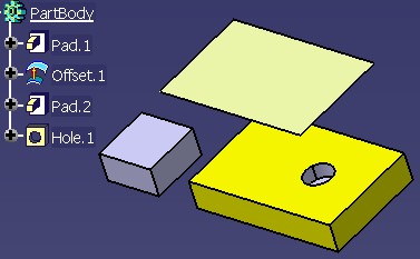
In V5R14, the Body feature is created from the HybridBody StartUp [Fig.1]. This name comes from the fact that this StartUp is able to contain surfacic features in addition of solid features. The picture [Fig.3] shows it.
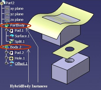 |
On the above picture, you can see that surfacic features (Surface.1,
Split.1 and Offset.1) are integrated into Body features (PartBody
and Body.2), and modify the solid features.
In CAA documentation, solid and surfacic features set, and solid features set is the wording used to designate a Body feature created after and before R14 respectively.
When opening a Part document containing features created from the MechanicalTool StartUp, no conversion will be done. It means that the former Body features remain solid features sets (their StartUp are always MechanicalTool), and you cannot insert surfacic features inside them. But in a former Part document, the new created Body features are instantiated from the HybridBody StartUp. So in the same Part document can coexist solid features sets, and solid and surfacic features sets [Fig.4].
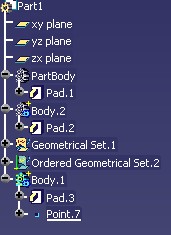 |
Just above, the picture is a screen shot of a Part document created before
the R14. PartBody and Body.2 are features instantiated
from the MechanicalTool StartUp, whereas Body.1 is a feature
instantiated from the HybridBody StartUp. The icons enables the end user to
differentiate them: the icon for the former body is gray, and for the new one it
is green:
|
|
|
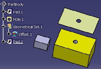
But excepted the icon color, what is the difference between the former body
(a MechanicalTool) and the new one (an HybridBody) ? Let's us consider two parts
with the same visual effect [Fig.6]. On left,
PartBody (the main body) is a former body (the icon is gray), and on
right it is a new body, its icon is green.
 |
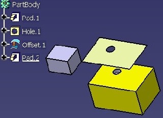 |
Offset.1 is holed in the two cases: the surface is based on the
top face of Pad.1.
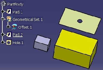
Now let us consider the following scenario: reorder Hole.1 to
locate it after Pad.2, and compare the result on [Fig.7].
On left it is the result with the MechanicalTool, and on right the result with
the HybridBody.
 |
 |
On left, you can see that Offset.1 is always holed. The reason
is that Offset.1 is always based on Hole.1. On right,
you can see that Offset.1 is no more holed. The reason is that now,
Offset.1 is based on the top face of Pad.1 which is
not holed.
This modification of behavior, is due to the fact that the surfacic and solid features set is an ordered set.
The Ordered Geometrical Set, and Body are geometrical features sets introducing two concepts:
This section is an overview on these two concepts, you are encouraged to read the referenced article [4] to find out more technical information.
The goal is having a set inside which features are ordered from the basic features (top) to features with huge historical graph (bottom). To reach it, a rule has been defined: "Each feature inside an ordered set can only have as input specifications features which are above it". It has been interactively implemented by following these behaviors:
The goal is having a set inside which only the relevant features are taken into account. Let us consider the following sample:
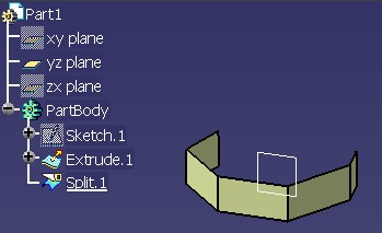 |
On the [Fig.8], just above, you can see in the 3D
viewer, even if Extrude.1 is not hidden (its icon is not
grayed), that only one surface is drawn. it is Split.1, the
surface coming from the split operation. Extrude.1 has been
like visually "absorbed" by Split.1. So feature such as
Extrude.1 are named absorbed features, and those as
Split.1 are named absorbent features.
So the main particularities of an absorbed feature are:
The interface which defines the type of a feature, is CATIInputDescription.
In all Mechanical Modeler articles, the wording to designate both the OGS and the Body feature, is "ordered set" in reference to these two concepts.
This section answers to three questions:
The following table [Tab.1] summarizes the possibilities, depending on the type of the geometrical features set (first row), and the type of the mechanical feature (the first column).
| Part | GS | OGS | Body | Solid Body (obsolete) | |
| GS | X | X |
X |
||
| OGS | X | X | X | ||
| Body | X | X | |||
| Solid Body (obsolete) | X | ||||
| Sketch | X | X | X | X | |
| Solid features | X | X | |||
| Point, Wire, Surface | X | X | X | ||
| Volume | X | X |
This above table essentially shows:
The CATIMechanicalTool interface creates the set and inserts it depending on the arguments of the methods. The usage of this interface is detailed in the referenced article [2].
For DS solid feature, the CATIPrtFactory interface manages the insertion, otherwise for DS surfacic features, or for your CAA features, the insertion into a geometrical features set is of yours responsibility. Here it is the methodology to follow depending on the type of the geometrical features set:
How to recognize this case: the former solid Body implements CATIMechanicalTool , but does not implement CATIGSMTool [Fig.1].
You aggregate the new solid feature with the InsertInProceduralView
method of the CATIPrtProceduralView interface. Then you update
the feature.
How to recognize this case: the GS implements CATIGSMTool and the
GetTypemethod of this interface returns0, or you can check that the set implements CATIMmiNonOrderedGeometricalSet [Fig.1].You aggregate the new geometrical feature (only a surfacic feature) with CATIDescendants, or you can also use the
InsertInProceduralViewmethod of the CATIGSMProceduralView interface. Then you update the feature.
How to recognize this case: all the ordered sets implement CATIGSMTool and the
GetTypemethod of this interface returns1. [Fig.1]You must respect the following steps:
- Aggregate the feature in the set
You have three possibilities depending on the type of the geometrical feature
- With the CATIDescendants interface for a surfacic feature
- At the end of the set, if the current feature is not inside this set
- After the current feature otherwise
- With the
InsertInProceduralViewmethod of the CATIGSMProceduralView for a surfacic feature. This method manages the position of the feature.- With I
nsertInProceduralViewmethod of the CATIPrtProceduralView for a solid feature. This method manages the position of the feature.- Update the new instance
- Call
Insert, the static method of the CATMmrLinearBodyServices classThis last method enables us to ensure the concept of absorption into the ordered set.
The aim of this section is to present the behaviors of the geometrical
features sets in term of result and copy. The following table [Tab.2]
summarizes the result of a copy as result (with or without link), and the
contents of the list returned by the GetResults method of the
CATIBodyRequest interface.
| Set Configuration (1) | Copy As Result without Link | Copy As Result with Link |
CATIBodyRequest |
| Solid Body | Solid feature |
Solid feature |
Solid feature + sketches |
| Solid Body1 BoolOp Solid Body2 |
Solid feature | Solid feature |
Solid feature + sketches of Solid Body1 + sketches of Solid Body2 |
| Body | Solid feature + surfacic feat. (- abs) | Solid feature | Such as Copy without link |
| OGS | Surfacic features (- absorbed) |
NA |
Such as Copy without link |
| GS | All surfacic features |
NA |
Such as Copy without link |
| OGS1 OGS2 |
surfacic feat.(-abs.) of OGS1 & OGS2 |
NA |
for OGS1: Such as Copy without link for OGS2 : E_FAIL |
| GS1 GS2 |
All surfacic elements of GS1 & GS2 |
NA |
for GS1: All surfacic elements of GS1 for GS2: All surfacic elements of GS2 |
| Body OGS |
Solid feature of Body + surfacic features (- abs.) of Body + surfacic features (- abs.) of OGS |
Solid feature | for Body: Such as Copy without link for OGS : E_FAIL |
| OGS Body |
surfacic features (- abs.) of OGS + Surfacic features (- abs.) of Body |
NA |
for OGS: Such as Copy without link + solid feature for Body : E_FAIL |
| Body1 OGS Body2 |
Solid feature of Body1 + surfacic features (- abs.) of Body1 + surfacic features (- abs.) of Body2 + surfacic features (- abs.) of OGS |
Solid feature | for Body1 : Such as Copy without link + solid feature of
Body2 for OGS and Body2 : E_FAIL |
Abbreviations or annotations:
This above table shows:
You can read the "Specification/Result Mechanism Applied to Mechanical Features" to have a complete view of the result of a set [6].
Since R13, with a Gso license, you can interactively create volumes. The following picture [Fig.9] is an illustration.
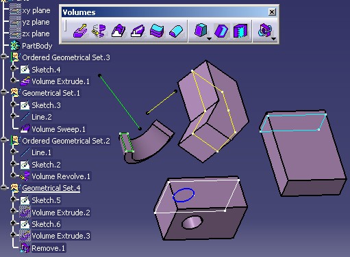 |
These features can only be inserted into a surfacic features
set: On [Fig.9] you can see that Volume Extrude.1,
defined from the blue sketch, is inside an Ordered Geometrical Set, and
Volume Sweep.1, defined from the yellow features, is inside a Geometrical
Set. It is not possible to create one in a Body.
Since R14, you can create them with CAA API.
With the CATIPrtFactory interface
To create a sweep, a revolve,... such as Volume Sweep.1,Volume
Revolve.1 on [Fig.9].
With the CATIGSMFactory interface
To create an Extrude such as Volume Extrude.1 on [[Fig.9]
To create Add, Remove, Intersect, Union Trim operations. The result of this operation is itself a volume.
Remove.1[[Fig.9] is a volume.
Volumes are surfacic features. The implementation of the
IsAShape method of CATIMf3DBehavior interface, answers S_OK.
To distinguish them from the other surfacic features (point, wire and surface),
there is the CATIMf3DBehavior2 interface and its IsAVolume
method, which answers S_OK for them.
Refer to the "Creating volume form features" and "Inserting boolean operation on volume features" use cases of the Generative Shape Design for more details about the volumes, their creation, and their usage.
Since R14, the specification tree reflects the internal modelization. It means that if a feature A is represented below a feature B, the feature A is aggregated by B. Have a look to the following picture [Fig.10] for an illustration of this new principle.
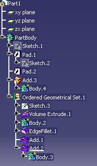 |
About the Sketches:
About the boolean operations:
|
Here are the screen shots of the Parent/Children command applied on
Pad.2 (left), Add.1 (middle), and Add.2
(right).
 |
 |
 |
[Top]
Since the R13, the main novelties in the Mechanical Modeler are:
[Top]
| Version: 1 [Mar 2004] | Document created |
| [Top] | |
Copyright © 2004, Dassault Systèmes. All rights reserved.