Mechanical Modeler |
Ordered Geometrical SetPresentation and usage of the Ordered Geometrical Set, a V5R13 novelty |
|
| Technical Article | ||
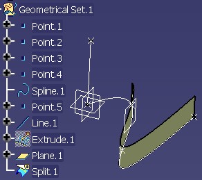
AbstractIn V5R13, Mechanical Modeler has renamed Open_Body in Geometrical Set, and introduced the Ordered Geometrical Set. The objective of this article is double: present the differences between them and expose the consequence, in term of code, of this novelty. |
Up to V5R13, the elements structuring [1] a Part document are:
In V5R13, two main modifications appear:
The Geometrical Set (GS) and the Ordered Geometrical Set (OGS) are both GSMTool features. This means that both of them are surfacic bodies, and contain surfacic geometrical features [2].
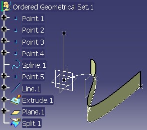
The GSMTool feature has been "typed" to be either a Geometrical Set or an Ordered Geometrical Set. This type is materialized by the downwards arrow on the icon representing the Ordered Geometrical Set in the specification tree.
In an interactive session, you can create either a Geometrical Set or an Ordered Geometrical Set using the Insert menu.
The Ordered Geometrical Set has been introduced to simplify the management of the links between features when the Part has a huge historical graph. The Geometrical Set staying always adapted for features with few history or without input specification (datum [2]).
Two main notions have been defined on the GSMTool to form an Ordered Geometrical Set:
The goal is having a body inside which features are ordered from the basic features (top) to the more complex features (bottom). To reach it, a rule has been defined: "Each feature inside an Ordered Geometrical Set can only have as input specifications features which are above it in the same set". The introduction of the current feature, which already exists for solid bodies (Part/PartBody), enable us to implement this rule.
The notion of absorbent feature is a novelty. There are features modifying other features. Their visualization makes useless the visualization of the modified features, since they are superimposed. Consequently, in an Ordered Geometrical Set, the modified features, named further absorbed and which are intermediate features, are not drawn.
These two notions are detailed below.
To force the end user to locate his features in a "logical" order into the ordered surfacic body, a feature can only rely on features (inputs) which are above it in the same body. It is the rule in order to have an ordered body.
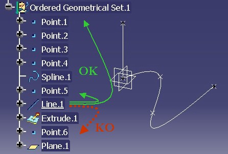 |
In this above picture, Fig.2, Line.1
can have Point.1 and Point.5 as inputs, but not Point.6,
since it is below Line.1.
Specific behaviors have been implemented to help the end user to respect the previous rule when designing its geometry.
Here are detailed these four behaviors.
 |
When Line.1 is edited, it becomes the current feature such as
shown by the above picture Fig.3. The name of the current feature is underlined in the specification
tree, such as using the "Define in Work
Object" interactive command.
Line.1 is the current feature, and you create a point.
The new feature will be inserted just below Line.1, as shown on
Fig.4, and not below Plane.1, the last feature of the Ordered
Geometrical Set.
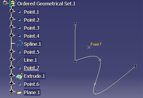 |
In a Geometrical Set, Point.7 would have been automatically
aggregated at the end of the current body. This behavior enables the end user
to locate its new feature into the Ordered Geometrical Set in order to respect
the top /down order.
The input specifications of a feature can be only features above it in the specification tree (if inputs are selected in the same body)
The CATFeatureImportAgent is an agent of selection mainly use in the Part and Product context. It has been modified to enable the end user selecting only the features above the current feature.
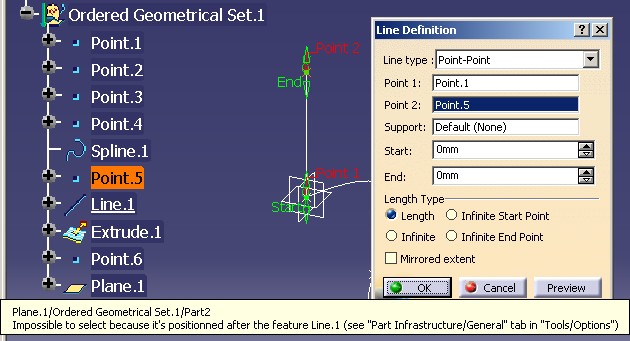 |
On this above picture Fig.5, Line.1 is being edited. When you try to
replace
Point.5 by Point.6, which is below Line.1 in the specification tree,
the following tool tip is displayed.
In the case of the creation of a feature, since the new feature is inserted just below the current one, the order rule will be kept.
The CATFeatureImportAgent agent can prevent the selection of features inside the same body. But you can always select a feature from another body below or above the current one, i.e. in another body.
At last, it must be specified that this rule of selection is only an interactive rule. By code, there is no protection on interfaces modifying the inputs of features.
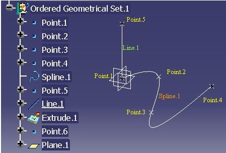
The following Fig.6 shows the 3D viewer when all the elements of the Ordered Geometrical Set, presented just above, Fig.2, are visible.
 |
It is the last element of the body which is the current feature, so all elements of the surfacic body are drawn.
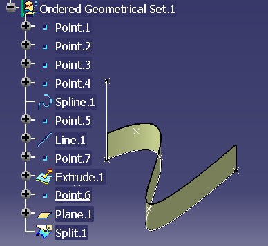
Now, if you observe Fig.7
where Line.1 is the current feature, from Point.1 to Line.1 the features in the
Ordered Geometrical Set are visualized, but not Extrude.1,
Point.6 or Plane.1.
 |
So if you are editing Line.1, you are not disturbed by the
features located below it, and you cannot select them in the 3D viewer.
Consequently, you cannot "break" the order rule by selecting in 3D.
The current feature enables us to manage the location of features into the surfacic body, to ensure a coherence into the specifications, and avoid to visualize the useless features when editing one. The current feature is managed by CATIPrtPart, an interface implemented by the Part feature [1].
Compare the following two pictures in Fig.8.
 |
 |
Both show the split of a
surface (Extrude.1) by a plane (Plane.1)- see Fig.4. The 3D visualization of the result
seems equal: you only see Split.1, and Extrude.1 is
not visible. But if you have a look to the specification tree, you can remark that on the left
picture, Extrude.1
has
the hidden icon, and on the right, its icon is
normal. It means that if you swap the visible space, Extrude.1
of the
Geometrical Set (on left) will be drawn, while Extrude.1 inside the Ordered Geometrical
Set
will not be.
Once Split.1 is created, Extrude.1 is visually
useless for the design. Split.1 is said to be an absorbent feature.
It means a feature which modifies one or several features. Conversely, Extrude.1
is named an absorbed feature.
There are four behaviors to consider:
Here are detailed these behaviors.
The visualization of the absorbed feature is depending on the current feature position:
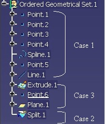 |
Fig.9 shows the three cases detailed below:
It is the general rule which is applied: Only
features above the current feature are visualized in the 3D viewer. Consequently, Extrude.1 is not visualized. See Fig.2
for an example.
Fig.10, shows that Point.6, the point between Extrude.1
(absorbed feature) and Split.1 (absorbent feature), is the current feature.
 |
You can notice that Extrude.1
is displayed. At this time (Point.6 current) of the history of
the OGS, Extrude.1
has not been yet modified by Split.1.
Split.1) or one feature below it.The Fig.8 shows that Extrude.1 is not
drawn.
Try to create an offset of Extrude.1 just below the Split operation Fig.8. It will be
impossible to select Extrude.1 whereas Extrude.1 is
above the new offset.
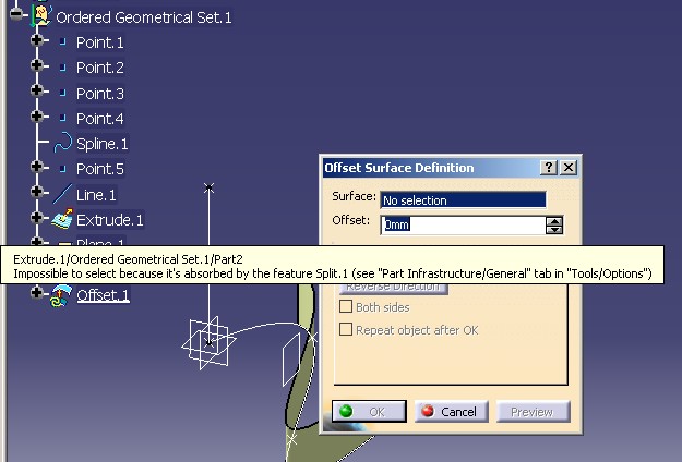 |
The CATFeatureImportAgent has been modified to prevent the selection of an absorbed feature. Thus, possibility to select in the specification tree is compliant with what is drawn in 3D. See the previous Absorbed Feature Visualization section.
Suppose that just after the Split operation of Extrude.1 by Plane.1
Fig.8 (after: time notion), you want introduce a
modification of Extrude.1 to do before the first Split (before:
location sense). To do that, first you set current Extrude.1
or Plane.1, and then you create Plane.2
and Split.2.
Here is the result of this scenario.
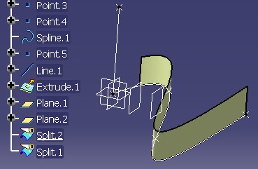 |
Since Split.2 is created between Split.1
and Extrude.1, Split.1 relies on Split.2
and no more Extrude.1. Before this operation, the input of Split.1 was Extrude.1, but after it is Split.2.
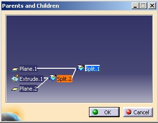
The Parent/Children command shows
that:
|
After Insertion of Split.2 |
Before Insertion of Split.2 |
 |
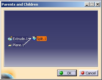 |
This modification of Split.1 is managed by a mechanism of feature insertion
in the Ordered Geometrical Set.
This mechanism is based on the Insert method of the CATMmrLinearBodyServices
class. It must be invoked whatever the type of the feature aggregated in the Ordered Geometrical
Set is. It must also be invoked if you reorder features inside an OGS, or if
you change their inputs.
Absorbed features do not have only visual behaviors. They do not appear in the result of the surfacic body. The CATIBodyRequest [3] interface which returns the result of a mechanical body will do not include the absorbed (intermediate) features.
Finally to finish with the absorbent features, it is the CATIInputDescription interface which gives the type of the feature, and in case of absorbent feature (feature of modification), this interface specifies the absorbed inputs.
To sum up, the Ordered Geometrical Set is a kind of surfacic body introduced to channel their contents, by imposing the orders of creation of features, and to avoid drawing the intermediate features. It should help the designer to create the object to be built.
This section has presented to you the main behaviors of the Ordered Geometrical Set. You are encouraged to read the article about the structural elements [1] to find out a more technical information.
[Top]
The introduction of the Ordered Geometrical Set may imply modifications on your existing code. This section has been built to resolve all the questions that you must you ask according to the kind of application.
Here are the four kind of applications:
The first level enables you to consult the contents of a Part document in order to perform analysis or to do data transfers. You should know how to retrieve the elements, and their geometrical result, of an Ordered Geometrical Set.
The interface to use is obligatorily CATIBodyRequest. This
interface returns all the geometrical features of the Ordered Geometrical Set
excepted the absorbed features (see the Absorbent Feature section). Nevertheless, if you need all the
aggregated geometrical features of the set, you can always use the GetDirectChildren
method of CATIDescendants with the CATIGeometricalElement3D
interface as filter.
The referenced article [3] explains the result of a surfacic body, the usage of the CATIBodyRequest interface, and how to retrieve the topological result (CATBody) of each element contained into the surfacic feature.
a/ If you are an application instantiating, and not defining, Dassault Systemes (DS) or CAA surfacic features. Your problem is where and how to store a new instantiation.
Once you have retrieved a GSMTool, checked it was not an Ordered
Geometrical Set, aggregate the new feature in the surfacic body thanks
to CATIDescendants.
If your application uses the CATIGSMProceduralView
interface, you should no more use the InsertInProceduralView
method which accepts the insertion of features in Ordered Geometrical
Set.
This option is possible only if the feature to insert can be stored in an Ordered Geometrical Set. For any surfacic DS feature it is possible, for a CAA feature verify that it implements CATIInputDescription.
Once you have retrieved a GSMTool, if it is a Geometrical Set you aggregate
the new feature with CATIDescendants, otherwise
you insert the
new feature in the Ordered Geometrical Set by the following methodology:
Append method)Insert, the static method of the CATMmrLinearBodyServices
classIf your application uses the CATIGSMProceduralView
interface, you can keep the usage of the InsertInProceduralView
method. This method manages the aggregation according to the type of the
surfacic body. For an Ordered Geometrical Set, the second (update) step
and the third (Insert) step remain your job.
You can you refer to the Combined Curve use case [4], where the two choices have been implemented.
b/ If you are an application modifying the contents of surfacic bodies, you
should take care of the CATIDescendants usage. If you aggregate (see
just previously), move, or modify features inside an OGS, you should then call the Insert method of the CATMmrLinearBodyServices
class to ensure the linearity into the set.
If you have an application instantiating Power Copy or User feature, you have nothing to do since the software of instantiation automatically manages the insertion into a body whatever its type. However, if you have implemented the CATIEdit interface on your "typed" user feature you should set as current the edited instance, and restore the old current feature once the edition is ended. You can refer to the CAAMcaUdfEdition use case [10], for a detailed implementation.
For those which have created a CAA Geometrical StartUp [6] or want create a new one, the only one question is "Do I want to store my feature in an Ordered Geometric Set" ?
You have to implement the CATIInputDescription interface on your StartUp. This interface enables you to define the type of the feature, absorbent feature or not, and to define its "absorbed" inputs.
On the CAA StartUp you have implemented a set of interfaces to complete or overload behaviors of a geometrical feature [8], and one of them is the CATIEdit interface to edit the feature. You should set as current the edited instance, and restore the old current feature once the edition is ended.
In interactive command creating new instance of your CAA StartUp:
You can refer to the Combined Curve use case for the implementation of the CATIInputDescription interface [7] and the creation and edition command [9].
You must check that all commands creating new instances do not allow to store new instances in Ordered Geometrical Set. Refer to the first case of the "Geometrical Feature Instantiation" section.
[Top]
Up V5R13, the surfacic body, a mechanical feature deriving from the GSMTool
StartUp, can be either a Geometrical Set, or an Ordered Geometrical Set. The
distinction is retrieval by the GetType method of the CATIGSMTool
interface. An Ordered Geometrical Set is characterized by the two following
notions:
Each feature can only rely on features aggregated above it in the specification tree; when the input specifications are into the same body.
Feature modifying one or more of its input specifications, is named a feature of modification. It is also named an absorbent feature because its modified features are like absorbed since they are not drawn in 3D, they do not appear in the result of the surfacic body.
For an existing or a new application, the most important things to retain are:
Insert method after each modification on inputs of
features aggregated into an OGS,[Top]
| Version: 1 [Oct 2003] | Document created |
| [Top] | |
Copyright © 2003, Dassault Systèmes. All rights reserved.