AbstractThis article discusses the CAAGsiBodyGSAndOGS use case. This use case explains how to create different types of Geometrical Set and instanciate features in them. |
This use case intends to illustrate creation of different geometrical feature sets , Geometrical features set are Body, GS(Geometrical Set) and OGS(Ordered Geometrical Set).
It illustrates also depending the current set or targeted set , shape design features insertion in the procedural view
[Top]
CAAGsiBodyGSAndOGS is a use case of the CAAGSMInterfaces.edu framework that illustrates how and where to insert shape design features in procedural view , it uses GSMInterfaces framework and MechanicalModeler framework capabilities .
[Top]
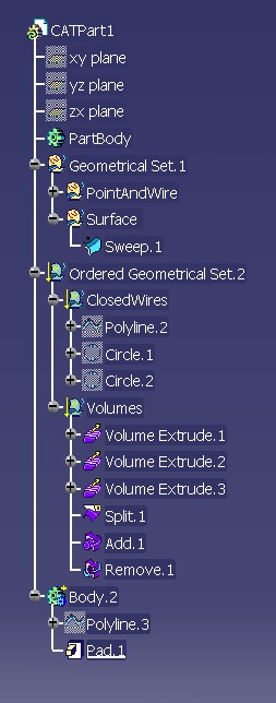
The use case creates the different type of set and insert features in it
[Top]
To launch CAAGsiBodyGSAndOGS, you will need to set up the build time environment, then compile CAAGsiBodyGSAndOGS along with its prerequisites, and set up the run time environment, and then execute the use case [1].
CAAGsiUserTools API is used in CAAGsiBodyGSAndOGS use Case
Launch the use case as follows:
e:>CAAGsiBodyGSAndOGS outputDirectory\CAAGsiBodyGSAndOGS.CATPart |
$ CAAGsiBodyGSAndOGS outputDirectory/CAAGsiBodyGSAndOGS.CATPart |
where:
outputDirectory |
The directory into which CAAGsiBodyGSAndOGS.CATPart is saved |
CAAGsiBodyGSAndOGS.CATPart |
The file that contains the part created to contain the nozzle shape result |
[Top]
The CAAGsiBodyGSAndOGS use case is made of main program located in the CAAGsiBodyGSAndOGS.m module of the CAAGSMInterfaces.edu framework:
| Windows | InstallRootDirectory\CAAGSMInterfaces.edu\CAAGsiBodyGSAndOGS.m\ |
| Unix | InstallRootDirectory/CAAGSMInterfaces.edu/CAAGsiBodyGSAndOGS.m/ |
where InstallRootDirectory is the directory where the CAA
CD-ROM is installed.
[Top]
There are six logical step in CAAGsiBodyGSAndOGS:
We will now comment each of those sections by looking at the code of the main method of file CAAGsiBodyGSAndOGS.
[Top]
CAAGsiBodyGSAndOGS sample first creates a session and opens the input CATPart.
Note: The important feature of the following sequence of code consists in the required call to the GetPart() method of the CATPrtContainer interfaces. This method allow to load in session the different containers of the part
...
// creates a session
char *pSessionName = "SampleSession";
CATSession *pSession = NULL;
rc = Create_Session(pSessionName, pSession);
if (NULL == pSession ) {
   cout<<" (CAAGsiBodyGSAndOGS) ERROR: Create_Session" << endl ;
   TestCaseError = 1 ;
}

// loads the document and initializes it
cout<<"The input document " << InputName << " is opened" << endl ;
CATDocument *pDoc = NULL;
rc =CATDocumentServices::OpenDocument(InputName, pDoc) ;

if (NULL == pDoc ) {
   cout<<" (CAAGsiBodyGSAndOGS) ERROR CATDocumentServices::OpenDocument" << endl ;
   TestCaseError = 2 ;
}

// Part Container
CATIPrtContainer *piPartContainer = NULL ;
CATIPrtPart_var spPrtPart;

if ( NULL != pDoc ) {
   // queries on the document to get the root container
   CATInit *pDocAsInit = NULL;
   pDoc->QueryInterface(IID_CATInit, (void**)&pDocAsInit) ;
   if ( NULL != pDocAsInit ) {

    // Extracts from document a reference to its part in hPartAsRequest
   piPartContainer =
      (CATIPrtContainer*)pDocAsInit->GetRootContainer("CATIPrtContainer");
   pDocAsInit->Release(); pDocAsInit = NULL ;

   if( NULL != piPartContainer ) {
      CATISpecObject_var spPart = piPartContainer->GetPart() ;
      spPrtPart = spPart ;
   }
}
...
|
Then in the initialization phase the wireframe and shape design factory , Part Design factory and Part Design Boolean factory are retrieved.
...
// Retrieve the Generative Shape Design Factory Interface
CATIPrtFactory_var spPrtFact;
CATIPrtBooleanFactory_var spBoolPrtFact;
CATIGSMFactory_var spGsmFact;
if ( NULL !=piPartContainer ) {
   CATIGSMFactory * _pFact =NULL;
   rc = piPartContainer -> QueryInterface(IID_CATIGSMFactory ,(void**)&_pFact);
   if (SUCCEEDED(rc) ) {
     spGsmFact = _pFact;
     if (_pFact) _pFact -> Release(); _pFact = NULL;
  }

  // Retrieve the Part Design factory Interface
   CATIPrtFactory * _pPrtFact =NULL;
   rc = piPartContainer -> QueryInterface(IID_CATIPrtFactory ,(void**)&_pPrtFact);
   if (SUCCEEDED(rc) ) {
       spPrtFact = _pPrtFact;
       if (_pPrtFact) _pPrtFact -> Release();
       _pPrtFact = NULL;
       }
    }
   CATIPrtBooleanFactory * _pBoolPrtFact =NULL;
   rc = piPartContainer -> QueryInterface(IID_CATIPrtBooleanFactory ,(void**)&_pBoolPrtFact);
   if (SUCCEEDED(rc) ) {
        spBoolPrtFact =  _pBoolPrtFact;
        if (_pBoolPrtFact) _pBoolPrtFact -> Release(); _pBoolPrtFact = NULL;
    }
}
....
|
[Top]
The Type of working tool is given as input in the sample
Three type of Geometric Feature set can be used for shape design features
- Body = Mechanical Tool that allow to aggregate Solid part design feature and Shape Design features = Points, Wires and Surfaces
- Geometrical Set = Shape Design features, Points, Wires, Surfaces and Volumes can be inserted , non ordered set , not rules of creation order in the set is imposed
- Ordered Geometrical Set := Shape Design features, Points, Wires, Surfaces and Volumes can be inserted , elements are ordered and if needed absorbed depending on related defined rule on the feature (implement of CATIInputDescription interface of MecmodInterfaces frameework - for exemple "Split" feature is a modification feature thus its main input is absorbed)
In the use case, we use a generic tool CAAGsiCreateGeometricFeatureSets to create Sets provided in
| Windows | InstallRootDirectory\CAAGSMInterfaces.edu\CAAGsiServices.m\ |
| Unix | InstallRootDirectory/CAAGSMInterfaces.edu/CAAGsiServices.m/ |
where InstallRootDirectory is the directory where the CAA
CD-ROM is installed.
 ...
// Create Geometric Features Set
//---------------------------------------------------------------
int Diag = -1 ;
CATISpecObject_var spSpecTool ;
CATISpecObject_var spParentTool ;
CATUnicodeString iName ;
iName="";

// Different type of tool are created in the sample
// -  TYPE_GeometricalSet
// -  TYPE_OrderedGeometricalSet
// -  TYPE_Body
iTypeOfTool = TYPE_GeometricalSet ;
spParentTool = NULL_var ;
rc = CAAGsiCreateGeometricFeatureSets (spCont, iName , spParentTool , spSpecTool , Diag , UNDER_Part , iTypeOfTool);
if (FAILED(rc)) {
   cout << "(CAAGsiBodyGSAndOGS) ERROR CAAGsiCreateGeometricFeatureSets = " << Diag << endl << flush;
   RetCode = 3 ;
}

...
|
Now we go into detail of the implementation of generic service creation CAAGsiCreateGeometricFeatureSets ( CAAGsiServices.m module)
Different cases can be identify depending of TopLevel , spParentForTool argument
 ...
// Reference Part
CATISpecObject_var spSpecPart = spPart;
CATISpecObject_var spParentForTool ;

// Tool is about to create under the Part
if (iTopLevel==1 ) {
     spParentForTool = spPart ;
}

// Tool is about to create under a defined Parent Tool
else if (iTopLevel==0 && spInputParentTool != NULL_var ) {

   CATIBasicTool_var spSpecBasicTool = spInputParentTool ; // Check given parent is is a tool
   if ( NULL_var != spSpecBasicTool ) {
          spParentForTool = spInputParentTool ;
     }
    ...
}

// Tool is about to create after current object in the Part
else if (iTopLevel==0 && spInputParentTool == NULL_var ) {

    //Retrieve the current tool
    CATIBasicTool_var spCurrentTool = spPart -> GetCurrentTool();

    spParentForTool = spCurrentTool;
    // Read Current feature : A tool has to be insert after the current feature
    CATISpecObject_var spCurrentFeat = spPart->GetCurrentFeature();

   // Set up the insertion position in the current tool
   // If he current feature is already a tool position =0 , insert at the end of the tool
   if ( spCurrentFeat != spCurrentTool) {
      // Read position of Current Feature in Tool
      CATIDescendants_var spRoot = spCurrentTool;
      Position = spRoot -> GetPosition( spCurrentFeat);
   }
}
...
|
Step2 : Check the targeted part is and available parent for the set to create
When the Geometrical features set is about to be insert under a targeted Parent (TopLevel ==0 ), we need to check that the whished type of tool is consistant
Ex: A Geometric Set (GS) can not be inserted under a Body .
Note :When parent is the Part (TopLevel == 1) we are sure to be able to create
whished tool
 ...
// Toplevel ==0  // Tools to be insert under a targeted  Parenttool
// Need to check the tool to insert is consistant with is Parent destination tool
if (iTopLevel==0) {

   CATIMmiNonOrderedGeometricalSet_var spNonOrderedGeomSet = spParentForTool ;
   CATIMmiOrderedGeometricalSet_var spOrderedGeomSet = spParentForTool ;
   CATIMechanicalTool_var spMechanicalSet = spParentForTool ;
   if (iType == 0 ) {
      if ( NULL_var != spNonOrderedGeomSet ) {
           oDiag = 0; // GS a inserer dans un GS ou sous un feature d'un GS
      }
      else {
           cout<<" (CAAGsiCreateGeometricFeatureSets) ERROR , a GS can only be inserted under another GS or directly under the part"<< endl ;
           oDiag =1 ; // GS que l'on veut inserer dans un Body ou OGS
      }
   }
   else if (iType == 1 || iType ==2 ) {
       if ( NULL_var != spOrderedGeomSet || NULL_var != spMechanicalSet ) {
           oDiag = 0; // Body or OGS , GS a inserer dans un Body or OGS
       }
      else {
           cout<<" (CAAGsiCreateGeometricFeatureSets) ERROR , a body or an OGS can only be inserted under another Body or OGS or directly under the part"<< endl ;
           oDiag =2 ; // Body or GS que l'on veut inserer dans un GS
    }
}
...
|
Create the set : Body, Geometrical Set or Ordered geometrical Set
 ...
// Create of the Tool
if (oDiag < 1) {
    // Phase 3: Create a GSMTool
    // ---------------------------------------------
    if (NULL_var != spParentForTool)
    {
       CATIMechanicalRootFactory_var spMechRoot = ispCont ;
       if (NULL_var != spMechRoot) {
       if (0 == iType ) {
          rc = spMechRoot -> CreateGeometricalSet(iName,spParentForTool,spSpecTool,Position);
       }
       else  if (1 == iType ) {
         rc = spMechRoot -> CreateOrderedGeometricalSet(iName,spParentForTool,spSpecTool,Position);
       }
       else  if (2 == iType ) {
         spSpecTool  = spMechRoot -> CreatePRTTool(iName,spParentForTool,Position);
    }

}
 ...
|
[Top]
Created Point , Wires or surface can be inserted in any of Body GS or OGS
 ...
// Create e Sweep Surface
CATIGSMSweepUnspec_var spExplSweep1 =
      spGsmFact -> CreateExplicitSweep(spSpecSpline1,spSpecPLine1,NULL_var , NULL_var , NULL_var );
CATISpecObject_var spSpecExplSweep1 = spExplSweep1 ;
CAAGsiInsertInProceduralView( spSpecExplSweep1 , NULL_var ) ;
rc = CAAGsiObjectUpdate(spSpecExplSweep1) ;
spPrtPart -> SetCurrentFeature(spSpecExplSweep1);
  ...
|
The generic tools CAAGsiInsertInProceduralView and CAAGsiObjectUpdate
(CAAGsiServices.m module ).
First directly call the InsertInProceduralView method of CATIGSMProceduralViwe
interface of GSMInterfaces framework,
Second call the Update on the feature and execute standard mechanical services
required for OGS and Body on feature.
Note that it is required then to set the feature as current , even if it has no
impact for insertion in GS , it will have for OGS and Body
Created of Shape design feature volume feature can be inserted in GS or OGS (volume creation requires GSO license)
Ex: If the set is a Body , only surfacic extrude can be insert in a Body
...
// Surfaces or volumes
// -------------------------------------------------------------

// --- Volume Features / Only to be insert in GS or OGS = Surfacic Set
CATGSMFeatureContextType GSDCreationContext ;

if ( TYPE_GeometricalSet == iTypeOfTool || TYPE_OrderedGeometricalSet == iTypeOfTool ) {
       cout<<" (CAAGsiBodyGSAndOGS) Create volumes / set is GS or OGS " << endl ;
       // -- Creation of feature in Volume context
       // Available Feature GSD Extrude / Revol / MultiSections Surfaces / Sweep
       // Note: Input profiles need to be closed curves or surfaces (check is done at feature build)
       GSDCreationContext= CATGSMVolumeCtxt;
}

else if (TYPE_Body == iTypeOfTool) {
       cout<<" (CAAGsiBodyGSAndOGS) Create surfaces / set is Body - No volume can be inserted " << endl ;
       // -- Creation of feature in standard Gsd context (Surfacic)
       GSDCreationContext= CATGSMSurfaceCtxt;
}


// Extrude 1
spCkeStart= CreateLength ( spCkeFact, "Start", 0 );
spCkeEnd = CreateLength ( spCkeFact, "End" , 100.0);
CATIGSMDirection_var Dir1 =spGsmFact -> CreateDirection ( spListPlane[1]);
CATIGSMExtrude_var spExtrude1 = spGsmFact -> CreateExtrude ( spSpecPLine , Dir1 , spCkeStart, spCkeEnd, TRUE) ;

//Init of the context
spExtrude1 -> SetContext(GSDCreationContext) ;

CATISpecObject_var spSpecExtr1 = spExtrude1 ;
CAAGsiInsertInProceduralView( spSpecExtr1 , NULL_var ) ;
CAAGsiObjectUpdate(spSpecExtr1) ;
spPrtPart -> SetCurrentFeature(spSpecExtr1);
...
|
[Top]
Save part and close the session
...
// save
if (NULL != OutputName )      {
    rc = CATDocumentServices::SaveAs  (*pDoc, OutputName );
    if (SUCCEEDED(rc))   {
            cout<<" (CAAGsiBodyGSAndOGS) Document saved " << endl ;
     }
     else {
            cout<<"ERROR in saving document" << endl ;
     }
}
// Closes the document
CATDocumentServices::Remove(*pDoc);

// Ends session and drops document
Delete_Session("SampleSession");
...
|
[Top]
This use case has demonstrated different solution and capabilities to create Body , GS or OGS and propose depending of obejct type different solution for insert
[Top]
| [1] | Building and Launching a CAA V5 Use Case |
| [2] | About Generative Shape Design Features |
| [3] | Inserting a Shape Design Feature in the procedural view |
| [4] | Updating a shape Design feature |
| [Top] | |
| Version: 1 [May 2004] | Document created |
| [Top] | |
Copyright © 2004, Dassault Systèmes. All rights reserved.