Equipment & Systems Engineering |
Electrical Harness Installation |
Managing Bundle SegmentsHow to create and connect bundle segments |
| Use Case | ||
AbstractThis article discusses the CAAEhiBundleSegment use case. This use case explains how to create a geometrical bundle and bundle segments and how to connect bundle segments. |
This use case is intended to show you how to create geometrical bundle and bundle segments, and connect bundle segments ( create a bundle segment network).
Following operations are detailed is this use case:
[Top]
CAAEhiBundleSegment is a use case of the CAAElecHarnessItf.edu framework that illustrates the ElecHarnessItf framework capabilities.
[Top]
The goal of CAAEhiBundleSegment is to create a geometrical bundle in a new CATProduct document. Bundle segments are created under geometrical bundle. Last step shows how to connect and disconnect bundle segment extremities.
[Top]
To launch CAAEhiBundleSegment, you will need to set up the build time environment, then compile CAAEhiBundleSegment.cpp along with its prerequisites, set up the run time environment, and then execute the sample. This is fully described in the referenced article [2].
To launch the use case, execute the following command:
mkrun -c "CAAEhiBundleSegment PathDir GbnName Bns1Name Bns2Name Bns3Name"
[Top]
CAAEhiBundleSegment code is located in the CAAEhiBundleSegment.m use case module of the CAAElecHarnessItf.edu framework:
| Windows | InstallRootDirectory/CAAElecHarnessItf.edu/CAAEhiBundleSegment.m |
| Unix | InstallRootDirectory\CAAElecHarnessItf.edu\CAAEhiBundleSegment.m |
where InstallRootDirectory is the root directory of your CAA V5
installation. It is made of a unique source file named CAAEhiBundleSegment.cpp.
[Top]
There are eight main logical steps in CAAEhiBundleSegment:
We will now comment each of those sections by looking at the code.
[Top]
Once the current session has been created, the CATProduct document is created into the session . pGbnDoc is a pointer to this document.
The root product of the document is retrieved . piRootProduct is a CATIProduct handle to the root product .
Methodology describing how to create a CATProduct document and how to retrieve the root product is described in [1].
[Top]
... CATIEleDocServices * piElecDocServices = NULL;
rc = pDoc->QueryInterface(IID_CATIEleDocServices,(void**) &piElecDocServices );
if ( SUCCEEDED(rc) && piElecDocServices )
{
rc = piElecDocServices->Initialize();
}
...
|
Initializing the electrical environment is mandatory to enable access to electrical objects or electrical attributes .
[Top]
Geometrical Bundle is created using CATEhiFactory interface on root product piRootProduct.
... CATIEhiGeoBundle * piGeoBundle = NULL; // the geometrical bundle // CATIEhiFactory * piEhiFactory = NULL; // the factory // rc = piRootProduct->QueryInterface(IID_CATIEhiFactory,(void**) &piEhiFactory ); // ... rc = piEhiFactory->CreateGeometricalBundle(&piGeoBundle); ... |
piGeoBundle is the pointer to geometrical bundle.
[Top]
First step is the creation of bundle segment part.
A new CATPart document is created and added into the product structure.
... CATIEhiBundleSegment * piBundleSegment1 = NULL;
rc = piGeoBundle->CreateBundleSegment (& piBundleSegment1 );
...
|
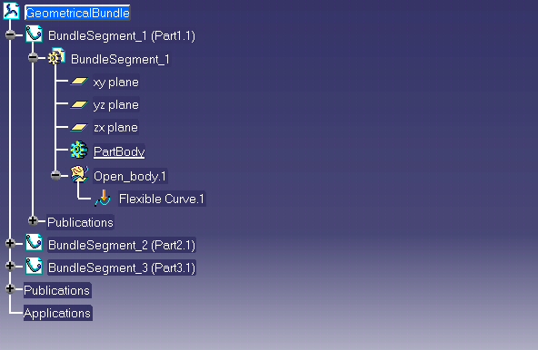
3 bundle segments are created : piBundleSegment1 , piBundleSegment2 , piBundleSegment3 are the pointers to the bundle segments instances.
Resulting tree is the following :
Second step is the definition of bundle segment computation parameters .
Bundle segment center curve is computed according geometrical parameters ( minimum bend radius, constraint points, tangency constraints ) and physical parameter ( gravity )
Two design methodologies are available : distributed slack or length mode.
Following attributes have to be defined :
Bundle segment 1 is created with length mode.
... double diameter, slack, length, bend_radius; CATUnicodeString mode; // + set attributes for bundle segment 1 diameter = 0.008; bend_radius=0.018; mode="Length"; length=0.106; rc = SetBundleSegmentAttributes ( piBundleSegment1, mode, slack, length, bend_radius, diameter ); ... |
Bundle segment 2 is created with slack mode.
... // + set attributes for bundle segment 2 diameter = 0.004; bend_radius=0.010; mode="Slack"; slack=1.5; rc = SetBundleSegmentAttributes ( piBundleSegment2, mode, slack, length, bend_radius, diameter ); ... |
CATIElecAttrAccess interface is used in SetBundleSegmentAttributes ( CAAEhiBundleSegment internal method ) to define bundle segment attribute values..
... HRESULT SetBundleSegmentAttributes ( CATIEhiBundleSegment * piBundleSegment, CATUnicodeString & mode, double & slack,
double & length, double & bend_radius, double & diameter )
{
HRESULT rc = E_FAIL;
//
if (!piBundleSegment) return rc; // pointer not valuated : exit E_FAIL
if ( mode != "Slack" && mode != "Length" && mode != "Bend" ) return rc; // invalid mode : exit E_FAIL
//
CATIElecAttrAccess * piElecAttr = NULL;
rc = piBundleSegment->QueryInterface(IID_CATIElecAttrAccess,(void**) &piElecAttr );
if ( FAILED(rc) || !piElecAttr ) return rc; // Query Interface CATIElecAttrAccess failed : exit E_FAIL
//
CATUnicodeString attribute;
// --- set build mode
attribute = "Elec_Creation_Mode";
rc = piElecAttr->Set(attribute,mode);
if ( FAILED(rc) ) return rc; // set attribute Elec_Creation_Mode failed : exit E_FAIL
// --- build mode = "Slack" : set slack
if ( mode == "Slack" )
{
attribute = "Elec_Di_Slack";
rc = piElecAttr->Set(attribute,slack);
if ( FAILED(rc) ) return rc; // set attribute Elec_Di_Slack failed : exit E_FAIL
}
// --- build mode = "Length": set length
if ( mode == "Length" )
{
attribute = "Elec_Length";
rc = piElecAttr->Set(attribute,length);
if ( FAILED(rc) ) return rc; // set attribute Elec_Length failed : exit E_FAIL
}
// --- set bend radius
attribute = "Elec_Bend_Radius";
rc = piElecAttr->Set(attribute,bend_radius);
if ( FAILED(rc) ) return rc; // set attribute Elec_Bend_Radius failed : exit E_FAIL
// --- set diameter
attribute = "Elec_Diameter";
rc = piElecAttr->Set(attribute,diameter);
if ( FAILED(rc) ) return rc; // set attribute Elec_Diameter failed : exit E_FAIL
//
rc = S_OK;
//
piElecAttr->Release(); // free memory
piElecAttr=NULL; // reset pointer value to NULL
//
return rc; // exit S_OK;
}
...
|
Third step is the definition of bundle route.
Using CATIGSMFactory, points are created in bundle segment part ( points coordinates are given in MKS unit )
SetBundleSegmentRoute is a sample internal method used to create points and add point to bundle segment curve. Input of method is the bundle segment and the coordinates of the points defining bundle segment route.
... double points[6]; int nb_point = 2; // +- P0 points[0]=0.; points[1]=0.1; points[2]=0.; // // +- define route for bundle segment 1 // +- P1 points[3]=0.; points[4]=0.; points[5]=0.; rc = SetBundleSegmentRoute ( piBundleSegment1, points, nb_point ); ... |
Bundle segment curve is retrieved using CATIEhiBundleSegment::GetElecCurve and points are added to curve with CATIGSMSpline::AddPoint
... HRESULT SetBundleSegmentRoute ( CATIEhiBundleSegment * piBundleSegment, double * point_coord,
int & nb_point )
{
HRESULT rc = E_FAIL;
//
if (!piBundleSegment) return rc; // pointer not valuated : exit E_FAIL
if ( nb_point < 2 ) return rc; // number of points < 2 : exit E_FAIL;
// -- retrieving electrical curve
CATIGSMSpline * pElecCurve = NULL;
rc = piBundleSegment->GetElecCurve(& pElecCurve );
if ( FAILED (rc) || !pElecCurve ) return rc; // electrical curve not found : exit E_FAIL
// -- retrieving container
CATIContainer_var spCont; // the container
CATISpecObject_var spObj = pElecCurve;
if ( NULL_var != spObj ) spCont = spObj->GetFeatContainer();
// -- retrieving factories :
// - litteral feature factory
// - GSM factory
CATICkeParmFactory_var spCKEfacto = spCont; // litteral feature factory
CATIGSMFactory_var spGSMfacto = spCont; // GSM factory
if ( NULL_var == spCKEfacto || NULL_var == spGSMfacto )
{
pElecCurve->Release(); // release pointe
pElecCurve=NULL; // reset pointer value to NULL
return rc; // cannot retrieve factories : exit E_FAIL
}
// -- retrieving GSM Body :
//
CATBaseUnknown_var spGSMBody = NULL_var; // the GMS body
CATIPartRequest * pPartAsRequest = NULL;
CATIPrtContainer_var spPartCont = spCont;
if ( NULL_var == spPartCont ) return rc;
CATISpecObject_var spPart = spPartCont->GetPart();
if ( NULL_var == spPart ) return rc;
//
if( SUCCEEDED(spPart->QueryInterface(IID_CATIPartRequest, (void**)&pPartAsRequest)) )
{
const CATUnicodeString stdContext(" "); // Sets the context for bodies lookup
// retrieve GSM open body
CATLISTV(CATBaseUnknown_var) surfBodies; // List of GSM bodies in pPartAsRequest
pPartAsRequest->GetSurfBodies(stdContext, surfBodies);
// select first body found to create points
spGSMBody = surfBodies[1];
pPartAsRequest->Release();
pPartAsRequest=NULL;
}
if ( NULL_var == spGSMBody ) return rc; // GSM body not found
CATIDescendants_var spFather = spGSMBody;
if ( NULL_var == spFather ) return rc;
// -- create and add points to curve
//
CATICkeParm_var X;
CATICkeParm_var Y;
CATICkeParm_var Z;
CATIGSMPointCoord_var spPoint;
//
for ( int i=1; i<=nb_point; i++ )
{
X = spCKEfacto->CreateLength ( "X", point_coord[ 3*(i-1)] );
Y = spCKEfacto->CreateLength ( "Y", point_coord[1+3*(i-1)] );
Z = spCKEfacto->CreateLength ( "Z", point_coord[2+3*(i-1)] );
spPoint = spGSMfacto->CreatePoint(X,Y,Z);
if ( NULL_var != spPoint ) // --- point created
{
spFather->Append(spPoint); // add point under GSM body in tree
CATISpecObject_var (spPoint)->Update(); // conmpute point geometry
// --- add constraint point to electrical curve
pElecCurve->Add(spPoint);
}
else
{
// --- point creation failed
pElecCurve->Release(); // release pointer
pElecCurve=NULL; // reset pointer value to NULL
return rc; // GSM point creation failed : exit E_FAIL
}
}
//
// -- update curve geometry
spObj->Update();
//
pElecCurve->Release(); // release pointer
pElecCurve=NULL; // reset pointer value to NULL
//
rc = S_OK;
//
return rc; // exit S_OK;
}
...
|
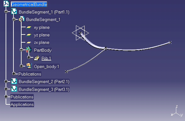
Fourth step is the computation of bundle segment representation.
CATIEhiGeoBundle::ComputeBundleSegment is used to compute bundle segment shape ( part design RIB ). This method may be used to re-compute shape after parameter modification.
... // + compute bundle segment 1 // rc = piGeoBundle->ComputeBundleSegment ( piBundleSegment1 ); ... |
[Top]
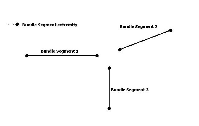
The 2 extremities ( connection points ) of each bundle segment are retrieved using CATIEhiBundleSegment::GetExtremities method.
... CATIEhiBnlSegmentExtremity * piBnlSegment1_Extremity1=NULL; CATIEhiBnlSegmentExtremity * piBnlSegment1_Extremity2=NULL; rc = piBundleSegment1->GetExtremities(&piBnlSegment1_Extremity1,&piBnlSegment1_Extremity2); ... CATIEhiBnlSegmentExtremity * piBnlSegment2_Extremity1=NULL; CATIEhiBnlSegmentExtremity * piBnlSegment2_Extremity2=NULL; rc = piBundleSegment2->GetExtremities(&piBnlSegment2_Extremity1,&piBnlSegment2_Extremity2); ... CATIEhiBnlSegmentExtremity * piBnlSegment3_Extremity1=NULL; CATIEhiBnlSegmentExtremity * piBnlSegment3_Extremity2=NULL; rc = piBundleSegment3->GetExtremities(&piBnlSegment3_Extremity1,&piBnlSegment3_Extremity2); ... |
[Top]
The goal of this step is to create a bundle segment network by connecting extremity 1 of each bundle segment.
Extremity 1 of bundle segment 1 and extremity 1 of bundle segment 2 are connected using connect method of CATIEhiBundleSegmentExtemity interface.
... rc = piBnlSegment1_Extremity1->Connect(piBnlSegment2_Extremity1); ... |

Extremity 1 of bundle segment 1 and extremity 1 of bundle segment 2 are connected .
... rc = piBnlSegment1_Extremity1->Connect(piBnlSegment3_Extremity1); ... |
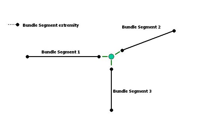
It is not necessary to connect bundle segment 2 and bundle segment 3 extremities. Extremity 1 of bundle segment 2 and extremity 1 of bundle segment 3 are also connected.
[Top]
Disconnect method of CATIEhiBundleSegmentExtremity is used to disconnect extremities.
Extremity 1 of bundle segment 1 is disconnected. Extremity 1 of bundle segment 2 and extremity 1 of bundle segment 3 remain connected.
... rc = piBnlSegment1_Extremity1->Disconnect(); ... |

[Top]
The four created documents are saved into directory defined as input. Name of file is the part number.
3 bundle segment parts are saved first.
... CATIProduct_var spBnsInstance; // bundle segment instance product CATIProduct_var spBnsReference; // bundle segment reference product CATILinkableObject_var spLinkable; // handle to retrieve document from object CATDocument * pBnsPartDoc = NULL; // bundle segment part document // --- saving bundle segment 1 CATPart document spBnsInstance = piBundleSegment1; if ( NULL_var != spBnsInstance ) spBnsReference = spBnsInstance->GetReferenceProduct(); if ( NULL_var != spBnsReference ) spLinkable = spBnsReference; if ( NULL_var != spLinkable ) pBnsPartDoc = spLinkable->GetDocument(); ... rc = CATDocumentServices::SaveAs (*pBnsPartDoc , PathOutput+Bns1File ); ... |
Geometrical bundle is saved at the end.
... rc = CATDocumentServices::SaveAs (*pGbnDoc , PathOutput+GbnFile ); ... |
Document is removed and session is deleted before exit.
... rc = CATDocumentServices::Remove(*pGbnDoc); ... rc = ::Delete_Session(sessionName); ... |
[Top]
This use case is has demonstrated how to create geometrical bundle and bundle segments, how to connect and disconnect bundle segment.
Following operations have been detailed is this use case :
Initialize method
of CATIEleDocServices.CreateGeometricalBundle
method of CATIEhiFactory.CreateBundleSegment
of CATIEhiGeoBundle.SetValue of CATIElecAttrAccess
.ComputeBundleSegment
of CATIEhiGeoBundle.GetExtremities
of CATIEhiBundleSegment.Connect of CATIEhiBundleSegment.connect of CATIEhiBundleSegment
.[Top]
| [1] | Adding Components to a Product Structure |
| [2] | Building and Launching a CAA V5 Use Case |
| [Top] | |
| Version: 1 [Feb 2002] | Document created |
| [Top] | |
Copyright © 2002, Dassault Systèmes. All rights reserved.