Equipment & Systems Engineering |
Electrical System Functional Definition |
Managing an Electrical SystemHow to create an electrical system in a Product document |
| Use Case | ||
AbstractThis article discusses the CAAEFDInterfaces use case. This use case explains how to create an electrical system feature that is bound to imbed Electrical Features. |
This use case is intended to help you make your first steps in programming with CATIA EFD Interfaces. Its main intent is to allow you to create an electrical system in a document.Before creating this system, you will have to navigate through the feature model of CATIA V5 to find the objects that will enable you to create this system (also called a EfdSystem) under the document.
[Top]
CAAEFDInterfaces is a use case of the CAAElecFunctionalItf.edu framework that illustrates ElectFunctionalItf framework capabilities.
[Top]
|
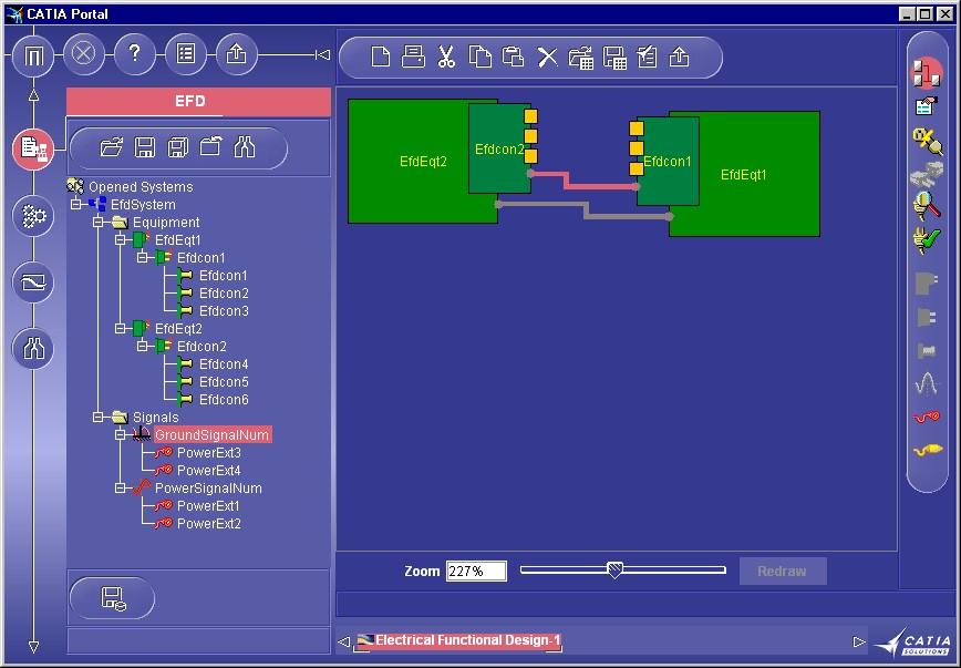
This picture represents a Product document created by the use case. The program creates an EfdSystem. The system contains two equipments, under each equipment one connector, under each connector three contact points, under the system you may also find two signals: a power signal and a ground signal, each signal has two extremities.
The goal of CAAEFDInterfaces use case is to show how to create an electrical system and its components, which is the first common step before creating the entire electrical system. We enrich the sample code CAAEFDInterfacesSample.cpp(.h) and illustrates some backbone concepts thats are shared by all electrical applications.
[Top]
To launch CAAEFDInterfacesSample, you will need to set up the build time environment, then compile CAAEFDInterfacesSample along with its prerequisites, set up the run time environment, and then execute CAAEfdElecSystem with the name you want to generate as argument [1].
[Top]
The CAAEFDInterfacesSample sample is made of a single class named CAAEFDInterfacesSample located in the CAAEfdElecSystem.m module of the CAAElecFunctionalItf.edu framework:
| Windows | InstallRootDirectory\CAAElecFunctionalItf.edu\CAAEFDInterfaces.m\ |
| Unix | InstallRootDirectory/CAAElecFunctionalItf.edu/CAAEFDInterfaces.m/ |
where InstallRootDirectory is the directory where the CAA CD-ROM
is installed.
This sample deals with the following classes:
| CATDocument | Class for the document base class |
| CATIEfdFactory | Class for the creation of electrical objects |
| CATIEfdSystem | Class for the electrical system |
| CATIEfdEquipment | Class for the electrical equipment |
[Top]
We will now first comment the EfdSystem and its components creation by looking at the code of the CAAEFDInterfacesSample. There are eight logical steps in CAAEFDInterfacesSample:
| # | Step |
| 1 | Create a Product document and retrieve it's root container |
| 2 | Create an electrical system |
| 3 | Create two electrical Equipments under the System |
| 4 | Create electrical connectors under the Equipments |
| 5 | Creates three contact points for each connector |
| 6 | Creation of two different Signals a power Signal and a Ground Signal under the system |
| 7 | Creation of signal extremities on the Power signal |
| 8 | Managing Equipment attributes |
The electrical system is displayed when the CAAEfdInterfacesSample
application is launched. The system creation and display is performed in the Electrical
Factory constructor that calls the CreateEfdSystem method. This
is described below.
[Top]
We need a CATInit interface pointer onto the Document feature to be able to get the current Root Container.
...
HRESULT RC = S_OK;
CATDocument *pDoc = NULL;
RC = CATDocumentServices::New("Product", pDoc);
...
CATInit *piInitDoc =NULL;
RC = pDoc->QueryInterface(IID_CATInit, (void**) &piInitDoc);
...
CATBaseUnknown *pCont = piInitDoc->GetRootContainer(CATIContainer::ClassName());
...
|
We first create a Product document, retrieve a pointer to CATInit onto this document, and retrieve from this pointer to CATInit a pointer to the document's root container.
[Top]
We need a CATIEfdFactory interface pointer onto the root container to create the electrical system.
... CATIEfdFactory *piEFDFactory = NULL; RC = pCont->QueryInterface(CATIEfdFactory::ClassId(), (void**)& piEFDFactory); ... CATIEfdSystem *piSystem = NULL; wchar_t* systemId =L"EfdSystem"; RC =piEFDFactory->CreateEfdSystem(systemId, &piSystem); ... |
We get the factory pointer from the root container, and then we create the
electrical system thanks to the CreateEfdSystem method of CATIEfdFactory.
The systemId character string is the electrical system name that
you can set to you own value.
[Top]
We need a CATIEfdEquipment interface pointer to be able to create the electrical equipment under the system.
... CATIEfdEquipment* piEquipment1 = NULL; wchar_t* eqt1Id =L"EfdEqt1"; RC =piSystem->AddEfdEquipment(eqt1Id, &piEquipment1); ... |
We create the electrical equipment under the system
[Top]
We need a CATIEfdConnector interface pointer to be able to create the electrical Connector under the equipment.
... CATIEfdConnector* piConnector1 = NULL; wchar_t* connector1Id =L"Efdcon1"; wchar_t* conNumber1Id =L"EfdconNum1"; RC =piEquipment1->AddEfdConnector(connector1Id,conNumber1Id, &piConnector1); ... |
We create the electrical connector under the equipment.
[Top]
We need a CATIEfdContactPoint interface pointer to be able to create the electrical ContactPoint under the connectors.
... CATIEfdContactPoint* piContactPt1 = NULL; CATIEfdContactPoint* piContactPt2 = NULL; CATIEfdContactPoint* piContactPt3 = NULL; RC =piConnector1->AddContactPoint(conPt1Id,conPtNum1Id, &piContactPt1); RC =piConnector1->AddContactPoint(conPt2Id,conPtNum2Id, &piContactPt2); RC =piConnector1->AddContactPoint(conPt3Id,conPtNum3Id, &piContactPt3); ... |
We create the electrical contact points under the connectors
[Top]
We need a CATIEfdSignal interface pointer to be able to create the electrical signals under the system..
... CATIEfdSignal* piSignalG = NULL; CATIEfdSignal* piSignalP = NULL; wchar_t* groundSignalId =L"GroundSignal"; wchar_t* groundSignalNum =L"GroundSignalNum"; wchar_t* powerSignalId =L"PowerSignal"; wchar_t* powerSignalNum =L"PowerSignalNum"; RC =piSystem->AddSignal(groundSignalId,groundSignalNum, &piSignalG); ... RC =piSystem->AddSignal(powerSignalId,powerSignalNum, &piSignalP); ... |
We create the electrical signals points under the system
[Top]
We need a CATIEfdSignalExtremity interface pointer to be able to create the electrical signal extremity under the equipment or under the connector
... CATIEfdSignalExtremity* piExtremityP1 =NULL; wchar_t* ExtremityId1 =L"PowerExt1"; RC =piSignalP->AddExtremity(piEquipment1,ExtremityId1, &piExtremityP1); ... CATIEfdSignalExtremity* piExtremityP3 =NULL; wchar_t* ExtremityId3 =L"PowerExt3"; RC =piSignalG->AddExtremity(piConnector1,ExtremityId3, &piExtremityP3); ... |
We create the electrical signal extremities points under the equipment or under the connector.
[Top]
We need a CATIElecAttrAcces interface pointer to be able to manage the electrical attributes.
...
CATIElecAttrAccess* piElecAttrAccess = NULL;
RC = piEquipment1->QueryInterface(CATIElecAttrAccess::ClassId(), (void**)& piElecAttrAccess);
...
CATUnicodeString pRefDesName = "Power Supply";
RC = piElecAttrAccess -> Set("Elec_Ref_Des", pRefDesName);
...
|
We have changed Equipment's name in "Power Supply".
[Top]
This sample case has demonstrated the way to create an electrical system in a document. We illustrate how some management interfaces on the system feature can be used like CATIEfdEquipment, CATIEfdConnector, CATIEfdSignal. We also illustrate the way to value the feature attributes in the list of its attributes using CATIElecAttrAccess.
[Top]
| [1] | Building and Launching a CAA V5 Use Case |
| [Top] | |
| Version: 1 [Sep 2000] | Document created |
| [Top] | |
Copyright © 2000, Dassault Systèmes. All rights reserved.