3D PLM Enterprise Architecture |
User Interface - Commands |
Subscribing to Mouse Move EventsAssociating a temporary graphic feedback with the mouse move |
| Use Case | ||
AbstractThis article shows how to subscribe, in a state dialog command to mouse move events and to create a temporary object that helps to figure out which object could be created if the end user clicks at the curent mouse location. |
This use case is intended to show how to subscribe to mouse move events to retrieve, in a state dialog command, a 3D point using its coordinates in the 3D space from the mouse current location on the screen, and to create from the retrieved point a temporary object to display that is updated at each mouse move event detection to follow the mouse move as if it were attached to the mouse. This object is a temporary circle in this example that helps the end user to see which circle would be created when clicking at the current mouse location. Temporary objects do not usually belong to the displayed document, and are displayed using the ISO (Interactive Set of Objects). Adding an object to the ISO automatically displays it, providing this object implements the CATI3DGeoVisu interface.
[Top]
The Circle command is a use case of the CAADialogEngine.edu framework that illustrates the DialogEngine framework capabilities.
[Top]
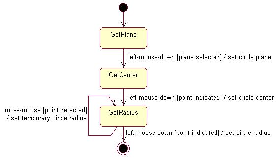
CAADegCreateCircleCmd is a state dialog command that creates a circle in the 3D space according to the following UML statechart diagram [1].
The dialog is as follows:
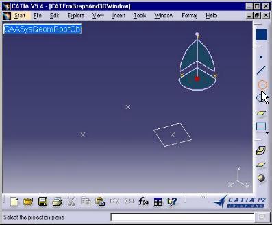 |
Select an existing plane that will be used as the circle plane. The active state becomes GetPlane. |
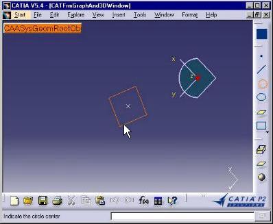 |
The viewpoint changes to make the selected plane and the screen plane coincide. The active state is GetCircle. |
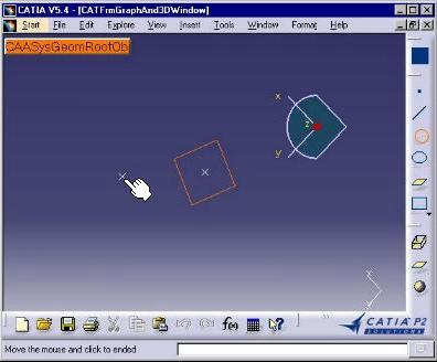 |
Click to indicate a point for the circle center. The active state becomes GetRadius. This image is captured just after the click. The indicated point is shown beside the plane. The mouse has not yet moved. |
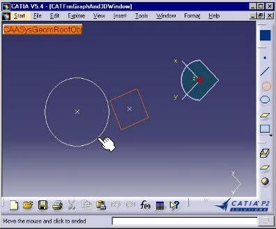 |
Move the mouse from this center. A temporary circle is drawn and increases or decreases to follow the mouse moves. The active state remains GetRadius. The self transition loops onto this state. |
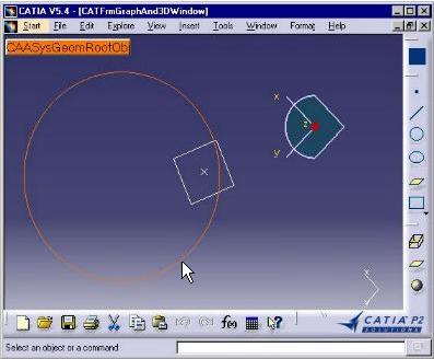 |
When the wished circle is obtained, click a point on this circle to actually create the circle. The command is now complete. |
Indicating a point means clicking on the screen at the desired location with the left mouse key. The command retrieves from this click a geometric point with coordinates expressed in the absolute axis system. This is made possible by assigning an indication agent [2] to the state that asks for indication. This indication agent is valued by the mouse click with a point computed from the pixel coordinates of the point clicked on the screen. This point is the projection of the clicked point in the screen plane onto a specific plane associated with the indication point and therefore named the projection plane [2]. In addition, the dialog agent can be valued without click if it is enabled for prevaluation. In this case, the simple mouse move is detected by the system and prevalues the dialog agent, that can then trigger a transition. If this is a self transition, a temporary object can be create from the point retrieved under the mouse. Moving the mouse makes the dialog loops on the state and continuously update the temporary object. A click can value the agent and trigger another transition that creates the actual circle and consequently ends the looping process.
The Circle command uses this means to create the temporary circle. The step-by-step describes the temporary circle creation.
[Top]
See the section entitled "How to Launch the CAAGeometry Use Case" in the "The CAAGeometry Sample" use case for a detailed description of how this use case should be launched.
Then, in the window where you run the mkrun command, do not type the module name on the command line, but type CNEXT instead. When the application is ready, do the following:
[Top]
The Circle command is made of a single class named CAADegCreateCircleCmd located in the CAADegGeoCommands.m module of the CAADialogEngine.edu framework:
| Windows | InstallRootDirectory\CAADialogEngine.edu\CAADegGeoCommands.m\ |
| Unix | InstallRootDirectory/CAADialogEngine.edu/CAADegGeoCommands.m/ |
where InstallRootDirectory is the directory where the CAA CD-ROM
is installed.
[Top]
To create the circle center, there are seven steps:
| # | Step | Where |
|---|---|---|
| 1 | Declare the indication agent | Header file |
| 2 | Instantiate the indication agent | BuildGraph method [3] |
| 3 | Set the indication agent projection plane | Transition action method SetPlane |
| 4 | Assign the indication agent to the GetRadius state | BuildGraph method |
| 5 | Create a self transition from/to the GetRadius state triggered by the indication agent valuation | BuildGraph method |
| 6 | Create the Temporary Circle and Add It to the ISO | Transition action method CreateCircleCenter |
| 7 | Update the Temporary Circle According to Mouse Moves | Transition action method UpdateCircle |
| 8 | Release the indication agent | Destructor or Cancel method |
[Top]
The state command class derives from CATStateCommand.
class CAADegCreateCircleCmd : public CATStateCommand
{
  ...
  private :
    CATIndicationAgent * _daIndicRadius;
    CATMathPlane         _ProjPlane;

    CAAISysPoint       * _TemporaryPoint ;
    CAAISysCircle      * _TemporaryCircle ;
    CATISO             * _ISO ;
    ...
|
A pointer to the indication agent, its projection plane, the temporary point to keep the indicated point, the temporary circle corresponding to this point, and the ISO, are declared as private data members.
[Top]
The indication agent is instantiated in the command BuildGraph
method.
void CAADegCreateCircleCmd::BuildGraph()
{
  ...
  _daIndicRadius = new CATIndicationAgent("GetRadiusPoint");
  _daIndicRadius->SetBehavior(CATDlgEngAcceptOnPrevaluate |
	         CATDlgEngWithPrevaluation | CATDlgEngWithUndo);
  ...
|
The character string GetRadiusPoint defined as the argument of the CATIndicationAgent constructor is the indication agent identifier. This identifier can be used to assign undo/redo prompts replacing the Undo and Redo items in the Edit menu. This is unused in self transitions. The indication agent behavior is set to enable it to be prevalued using CATDlgEngWithPrevaluation, and to trigger a transition when prevalued using CATDlgEngAcceptOnPrevaluate. It can also be valued and therefore can be undone without recording an undo step using CATDlgEngWithUndo.
[Top]
The SetPlane method is the action method associated with the
transition that retrieves the selected plane and use it to change the viewpoint.
It is the appropriate place to assign this plane as the indication agent
projection plane, since the plane selected is not kept as a data member.
CATBoolean CAADegCreateCircleCmd::SetPlane(void *iDummy)
{
  ... // Retrieve the origin and axes of the selected document plane
  CATMathPoint     PlaneOrigin;
  CATMathDirection U, V;
  modelplane->GetOrigin(PlaneOrigin);
  modelplane->GetPlane(U,V);

  // Set these retrieved origin and axes to the _ProjPlane
  _ProjPlane.SetOrigin(PlaneOrigin);
  _ProjPlane.SetDirections(U,V);

  // Set _ProjPlane as the indiation agent projection plane
  _daIndicRadius->SetMathPlane(_ProjPlane);
  ...
|
The plane selected in the document is retrieved in modelplane.
Its origin and directions are retrieved using the methods of this object, and
are set to _ProjPlane using the SetOrigin and SetDirections
methods of the CATMathPlane class. Then _ProjPlane is set as the
indication agent projection plane.
[Top]
Still in the BuildGraph method, the GetRadius state is created,
and the indication agent is added to this state. This makes it possible to value
the indication agent when this state becomes the active one.
  ...
  CATDialogState *stGetRadius = AddDialogState("stGetRadiusId");
  stGetRadius->AddDialogAgent(_daIndicRadius);
  ...
|
The AddDialogState method creates a new dialog state and adds it
to the states managed by the dialog command. The AddDialogAgent
method adds the indication agent to the state.
[Top]
The self transition is created in the BuildGraph method. This
transition is triggered when the indication agent is prevalued, that is when the
end user moves the mouse. The guard condition is checked, and if it returns
True, the action is performed.
  ...
  CATDialogTransition *pRubberTransition = AddTransition
	(
	  stGetRadius,
	  stGetRadius,
	  IsLastModifiedAgentCondition(_daIndicRadius),
	  Action((ActionMethod) & CAADegCreateCircleCmd::UpdateCircle)
	) ;
  CATDialogTransition *pThirdTransition = AddTransition
        (
	  stGetRadius,
	  NULL,
	  IsOutputSetCondition(_daIndicRadius),
	  Action((ActionMethod) & CAADegCreateCircleCmd::NewCircle)
        ) ;
...
|
The AddTransition method creates a transition and adds it to the
transitions managed by the dialog command. Pointers to the transition's source
and target states are the first and second arguments respectively. The same
pointer is used to create a self transition. The transition trigger is defined
in the guard condition as the condition to be checked using the IsLastModifiedAgentCondition
method applied to the indication agent. When the dialog agent prevalue is
modified, the transition fire. In this case, the UpdateCircleCenter
action method is executed. To get out of the loop, the end user clicks a point.
The second transition is then triggered because the indication agent is then
valued, and not prevalued. The trigger is defined using the IsOutputSetCondition
method. This transition has the final state as target state, and the action is
to create the circle in the document.
[Top]
When the end user has clicked to indicate a point, the transition between the GetCenter and GetRadius states is triggered, and if the guard condition returns True, the following action method executes.
CATBoolean CAADegCreateCircleCmd::CreateCircleCenter(void * iData)
{
  ... // Create the circle center, and creates the temporary circle
  ... // using this center, the projection plane, and a null radius
  _ISO->AddElement(_TemporaryCircle);
  ...
  return TRUE ;
}
|
The temporary circle is created using the indicated circle center in the projection plane shared by the different indication agents. This projection plane is the plane where the circle lies. To enable the temporary circle to be displayed, it should implement the CATI3DGoVisu interface. In addition, to be displayed as a non document object, it should be simply added to the ISO using the AddElement method.
[Top]
When the end user has clicked to indicate a point, the transition between the GetCenter and GetRadius states is triggered, and if the guard condition returns True, the following action method executes.
CATBoolean CAADegCreateCircleCmd::UpdateCircle(void * iData)
{
  // Gets the current Point
  CATMathPoint2D point2D = _daIndicRadius->GetValue();
  CATMathPoint Mouse ;
  _ProjPlane.EvalPoint(point2D.GetX(),point2D.GetY(),Mouse);

  // Computes the radius
  _Radius = (float) _CircleCenter.DistanceTo(Mouse);

  // Modification of the temporary circle
  _TemporaryCircle->SetRadius(_Radius);

  _ISO->UpdateElement(_TemporaryCircle);

  // Required to continue the rubber banding
  _daIndicRadius->InitializeAcquisition();

  return TRUE ;
}
  ...
|
The indication agent is prevalued by the mouse move. Its prevalue is a 2D
point located on the indication agent projection plane, obtained by the
projection of the point corresponding to the current mouse location on the
screen along a line passing through the viewpoint eye and the current mouse
location onto the projection plane. The indication agent GetValue
method retrieves this 2D point whose coordinates are expressed according to the
projection plane axis system. Then the CATMathPlane EvalPoint
method creates a 3D point from these coordinates. The temporary circle and its
radius were instantiated in the action method of the transition that creates the
circle center. The distance between the circle center to this point is computed
thanks to the DistanceTo method and set as the circle radius. Then
the ISO is updated.Using the retrieved point, the you can use the 3D point as
you wish, for example retrieve its coordinates expressed with respect of the 3D
global axis system.
[Top]
A pointer to the indication agent was created in the command BuildGraph
method as a data member to be accessed and used in different methods. It should
be released when it becomes useless. This can be done in the command destructor,
as shown here. This could also be done in the Cancel method called
just before the destructor.
CAADegCreateCircleCmd::CAADegCreateCircleCmd()
{
  ...
  if (_daIndicRadius) _daIndicRadius->RequestDelayedDestruction();
  _daIndicRadius = NULL ;
  ...
|
[Top]
This use case shows the objects involved to subscribe to mouse move events,
create a self transition that updates a temporary object added to the ISO
(Interactive Set of Objects) to display the object that would be created if the
end user decided to click at the current mouse location. These objects are the
statechart and its implementation in the BuildGraph method, the
states, the indication dialog agent and its projection plane, the transition
along with its condition and action, the way to retrieve a usable 3D point from
the pixel under the mouser, and the ways to add a temporary object to the ISO
and to update it.
[Top]
| [1] | Describing State Dialog Commands Using UML |
| [2] | Managing Indication |
| [3] | Implementing the Statechart Diagram |
| [Top] | |
| Version: 1 [Jan 2000] | Document created |
| [Top] | |
Copyright © 2000, Dassault Systèmes. All rights reserved.