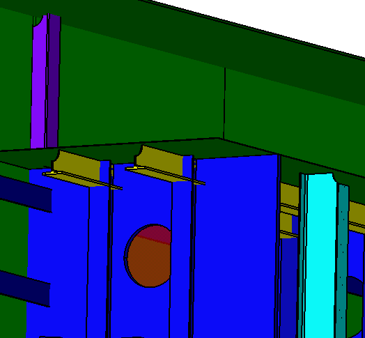
The procedure, described below, applies to both the Structure Detail Design and Structure Functional Design applications.

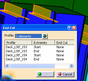
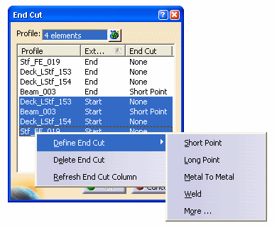
The two stiffeners are highlighted and their names (Profile), Extremities, and End Cuts are displayed in the End Cut dialog box.
Select the beam and the stiffener on free edge in the 3D session. Both these profiles are highlighted and their details are displayed in the End Cut dialog box.
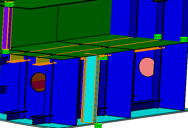
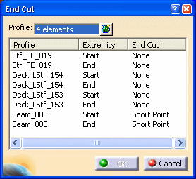
You can also pre-select all the profiles and then click the End Cut button.
In the End Cut dialog box:
- Press Ctrl and select each extremity manually.
- Sort the extremities by clicking Extremity and then using the Shift key select the extremities.
In the 3D session:
- Click to select each extremity manually. It gets highlighted in the End Cut dialog box.
- Click close to one extremity. All the extremities in its close proximity get selected. These appear highlighted in the End Cut dialog box.
The name of the selected end cut appears in the End Cut dialog box. In the example given below, Web-Snipe-Radius-R1 end cut is placed on all the selected profiles.

The image below shows the end cut placed on all the profiles.
