Most of the steps, described below, apply to both the Structure Detail Design and Structure Functional Design applications. Where indicated, specific steps apply to just one of the applications.
Select a bracket type from the Object drop down list, or select More to display the Catalog Browser.

Double-click Small Assemblies and a list of available Structure workbenches display.

Double-click the appropriate application and a list of available small assemblies display.
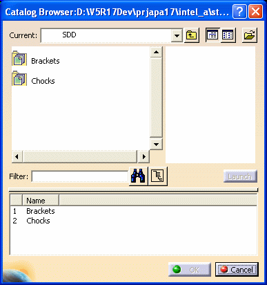
Double-click Brackets, then select the bracket type, and click OK.
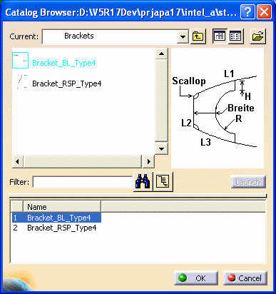
The Small Assemblies dialog box displays. The support and other inputs for the bracket type display under the Inputs column. Also, an image of the bracket type displays.

3.
Select Support and right-click, then select Select Reference Plane.
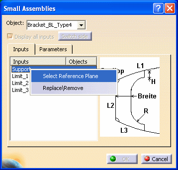
The Plane Systems dialog box displays.
See Basic Navigation for information on using the Plane Systems dialog box, also known as the Reference Plane Browser.
Select a plane system from the Select System drop down list, and then select as many reference planes as required from the list in Select Planes.

Click OK and the Small Assemblies dialog box displays the selected number of reference planes for the support under Objects, displayed as elements.
You can also make selections in your 3-D session. Select the reference planes. Each time you select a plane, the number of planes for the support increases, and displays under Objects, displayed as elements.
Select each limit under the Inputs column, and select in the 3-D session where appropriate. Your selection displays under Objects.
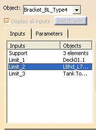
You can change Objects for the Inputs by selecting the limit, and then making another selection in the 3-D session.
When you select one or more supports, your 3-D session previews where the brackets are being placed. As you select each limit under the Inputs column, and select in the 3-D session, the preview indicates the orientation for the bracket placement.
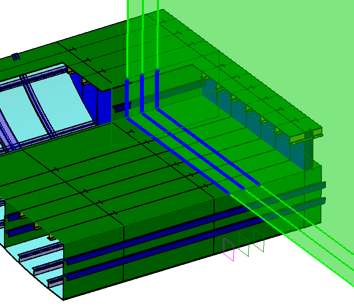
If the orientation for the selected limit is not the one desired (as in the the example below), you can switch sides.

Click the the Switch Side button and the orientation switches.
NOTE: In a Structure Detail Design 3-D session, the Switch Side button will not be available because the object has thickness. You need to select the correct face of the object in the 3-D session to switch the orientation.
After switching sides and selecting the third limit, you see the following:

NOTE: In Structure Functional Design, an arrow indicates the orientation. Clicking the arrow (or clicking the Switch Side button) switches the orientation.
To place chocks, you need to select Support and Shape as inputs. Support is the reference plane and Shape is the object on which you want to place the chock. In the given example, a chock is supported by CROSS.11 and is placed on a deck longitudinal stiffener.

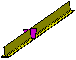
Selecting a shape and support for placing a chock results in an error, if the faces of the selected shape do not match the faces required as input. In such a case, Display all inputs helps you manually select the faces corresponding the input faces. Select the Display All Inputs checkbox. All the faces required as inputs for placing the chock are displayed. Select the corresponding faces of the shape in your 3 D session. Your selection appears as Objects.

Display all inputs is especially useful when your shape has more faces than those required for placing the chock. This function allows you to manually select the faces along which you want to place the chock.
Right click on Support, and select Replace/Remove.

The Elements List displays, listing the planes you originally selected.

You can replace a plane on the list with another plane. Select the planes/elements you want to replace and click the Replace button. Select a plane in the 3-D session, and this plane displays on the Elements List in place of the original plane.
You can also remove planes from the list. Select the planes/elements you want to remove, and click the Remove button. The selected planes are removed from the Elements List.
Click Close when you have made all the necessary changes.
You see the selected number of brackets placed in your 3-D session.
The following displays in a Structure Detail Design 3-D session.
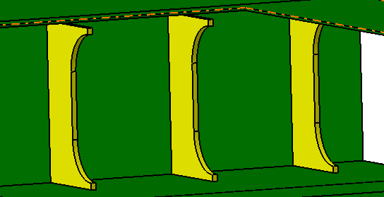
The following displays in a Structure Functional Design 3-D session.
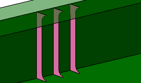
In the specifications tree, click the plus sign next to the bracket to expand the tree and display the support. Click the plus sign next to the support to display the parameters.
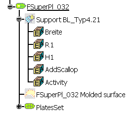
Double-click the support in the specifications tree to display the Definition of Support dialog box.
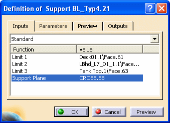
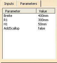
Select the Parameters tab and the parameters are available for you to modify.

You can enter other values, or change the values by clicking the arrow buttons.
Click OK after modifying the parameters. The bracket in your 3-D session reflects the parameter changes.
Additionally, you can double click a parameter in the specifications tree to display the Edit Parameter dialog box.

You can enter another value for this parameter, or change the value by clicking the arrow buttons. Click OK after modifying the parameter. The bracket in your 3-D session reflects the changed parameter.