This task explains how to view selected interferences in a separate viewer. It also explains how to use the Show / Show visualization filter (P2 only).
Insert the following sample cgr files: ATOMIZER.cgr, BODY1.cgr, BODY2.cgr, LOCK.cgr, NOZZLE1.cgr, NOZZLE2.cgr, REGULATION_COMMAND.cgr, REGULATOR.cgr, TRIGGER.cgr and VALVE.cgr.
They are to be found in the online documentation file tree in the common
functionalities sample folder cfysm/samples.
Step-by-Step Scenario
-
Select Insert > Clash from the menu bar or click the Clash icon
 in the DMU Space Analysis toolbar to
run a check of type Contact + Clash inside one selection comprising
Valve and Body1.The Check Clash dialog box expands to show the
results of the initial computation. The first interference is
selected by default and a detailed computation has been run.
Note: The results given in the various tabs in the dialog box correspond to the worst case.
-
Click Results window
 in the Check Clash dialog box to view the selected
interference in a dedicated viewer.
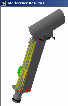
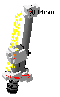
 The Interference Results window opens. By default, the detailed computation mode is set to Element level. Triangles identifying contacts and clearances, intersection curves identifying clashes and the penetration depth or minimum distance are computed and displayed.
Object viewing commands and commands in the Window menu are available in this window. You can, for example, tile the Interference results window and the original document window vertically or horizontally.
-
Select Window > Tile Vertically from the menu bar to organize the open windows vertically.
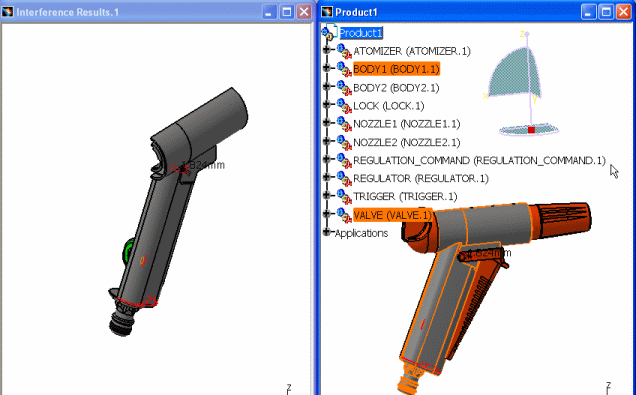
-
Click More in the Check Clash dialog box to access visualization filters.

Available in P2 configuration
-
(optional) Specify a new clash font size if necessary (Tools > Options > DMU Space Analysis > DMU Clash)
For example, if you specify 10 for the clash value font size, the new value size specified is automatically taken into account. 
This is what you obtain: 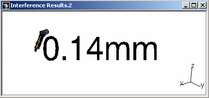

Clash values display is not impacted by the zoom command nor participate to the Fit in All functionality -
Select Show / Noshow in the drop-down box:
Only the valve (product 1) is visible. The body (product 2) is hidden.
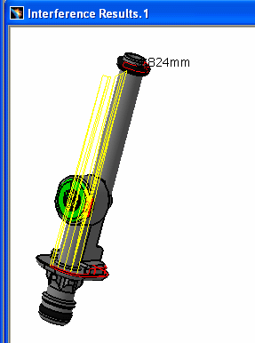
-
Select Noshow / Noshow in the drop-down box: Geometries of both products are hidden. The graphics representations of interferences only are displayed.
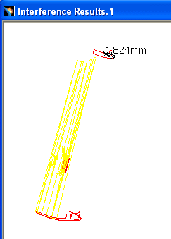

See Finer Analysis to find out how other visualization filters work and how to read detailed results. You can also export and publish clash command results.
-
Click OK in the Check Clash dialog box to exit when done. Interference results are kept as specification tree features.
Color Coding for Conflicts
-
Clash: red intersection curves identify clashing products.
-
Contact: yellow triangles identify products in contact.
-
Clearance: green triangles identify products separated by less than the specified clearance distance.
|
|
P2 Capabilities
Computing and Displaying Clash Results as an Intersection Volume
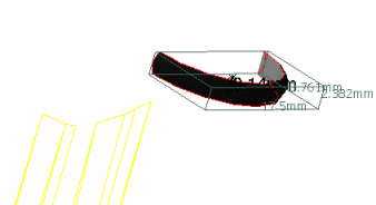
In DMU-P2, you can compute and display clash results as a voxel volume or a boolean solid. To do so:
-
Select Tools > Options..., Digital Mockup > DMU Space Analysis, DMU Clash - Detailed Computation tab
-
Select the type of volume of interest under Intersection Volume
-
If you selected Voxel, set the voxel size.
The voxel size is the edge-length of the voxel or cube. A lower value will give you a more accurate result but will also require a longer computation time and more memory. -
Click OK in the Options dialog box when done.
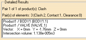
The intersection volume is also given in the Detailed Results box of the Check Clash dialog box.
More about Intersection Volume
computation and Display with Boolean option
The intersection volume computation is launched (during detailed
computation step) only if a clash is detected.
If a contact is
detected (the sag being taken into account), no computation is
performed for the intersection volume.
The two bodies involved in the computation can be of two types: volumes or surfaces.
Let's consider three cases
Two volumes
- The result corresponds to the intersection between the two considered volumes and can be one or more volume entities.
|
|
Note: if one of the volume is not watertight, the computation for the intersection volume may not give correct results. |
| Example 1 | |
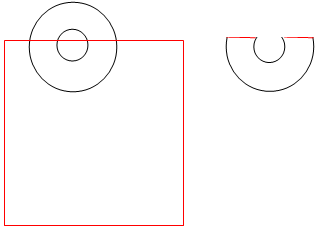 |
|
| Result: one single volume entity | |
| Example 2 | |
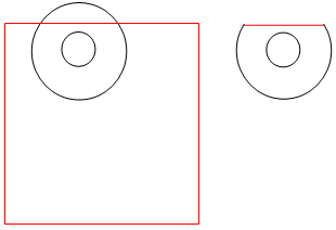 |
|
| Result: a single volume entity | |
| Example 3 | |
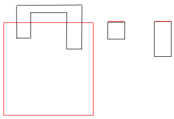 |
|
| Result: two volume entities. An inertial box is created for each volume entity. | |
One volume and a surface
The result is a surface or a set of surfaces| Example 1 (cross-sectional view) |
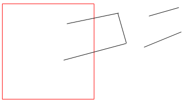 |
| Result: a surface with two components |
| Example 2 (cross-sectional view) |
 |
| Result: a surface |
Two surfaces
The intersection volume computation is not triggered.
|
|
Notes:
|
Voxel volume example::
|
Boolean solid example:
|
|
|
|
|
|
|
Computing and Displaying Contact and Clearance Results as Surfaces
In DMU-P2, you can compute and display contact and clearance results as surfaces (rather than triangles). To do so:
-
Select Tools > Options..., Digital Mockup > DMU Space Analysis, DMU Clash - Detailed Computation tab
-
Click Surface under Contact & Clearance Results
-
Set the accuracy, then click OK in the Options dialog box.
The accuracy entered defines the maximum value for the length of the longest side of a triangular representation of the results. This representation is used to obtain the yellow and green surfaces. -
In DMU-P2, the interference definition is also kept.
Using Visualization Filters
Visualization filters offer a more precise display in the Interference Results window.
-
All products: displays all products selected in the list.
-
Product: displays products involved in the current conflict.
-
Element: displays elements involved in the current conflict. Pairs of elements are listed in the Detailed Results box and can be browsed using the Next and Previous options.
Note: The Element option is only available if the detailed computation mode is set to Element level. This option is particularly useful when in Design mode. -
Show / Show drop-down box: a variety of combinations lets you better visualize the geometries of the two products involved in the conflict.
-
All cases drop-down box: lets you select the graphics representation you want to see displayed (All cases, None or Worst cases). If Element is selected, the Worst case option is not available.
Note: The effects of all options, except the Show / Show drop-down box, can be seen in the Preview window.
The graphic display (minimum distance or penetration depth) of the current result is kept when you exit the command. If you subsequently edit the results, the system re-displays the last current result analyzed.
|
|
Note: Clicking Deselect in the Check Clash dialog box removes the current results from the selection. |
Saving viewpoints
The different viewpoints set using the mouse ( zoom,
rotate, etc.) in the Interference Results window are also saved when you
exit the command. If you subsequently edit the results, the system
re-displays pairs of products from the last viewpoint set. Note, however,
that:
-
This applies when interferences are viewed via the List by Conflict tab
-
Viewpoints are not saved in the document and are therefore only valid for the duration of your session.
![]()
