|
This task shows you how to create subdivision surfaces by
extruding a curve along a direction. |
 |
A .CATPart document must be open. |
 |
-
Click Extrude
 in Creation toolbar (Sweep Primitives
sub-toolbar).
in Creation toolbar (Sweep Primitives
sub-toolbar).
 |
You can also access this command by
pressing ALT+SHIFT+Z. |
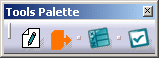
The following Tools Palette
along with screen for curve creation are displayed.
|
| |
Creating a Curve
|
| |
-
Click
Add Point
 to begin drawing the curve.
-
Click to add
points and draw the curve. The entire curve is drawn so that all options
available in Tools Palette can be described in this section.
|
|
You can also access this command by
pressing CTRL+SHIFT+S. |
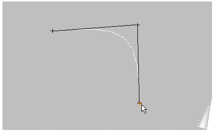
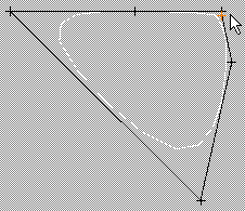
- The created points define the polygon of the
curve of subdivisions.
- The surface can be previewed as the points
are created.
- When a point is added, it can be moved as
long as you keep the left mouse button pressed.
|
|
| |
Adding New Points
|
| |
-
Add a new point on existing curve by clicking the left
mouse button at the required position. The point can be previewed on the
existing curve.
Once the point is created the surface is immediately previewed.
|
| |
Manipulating the
Points
|
| |
-
Click Move Point
 to move the point. The point closest to the mouse is manipulated.
|
|
You can also access this command by
pressing CTRL+SHIFT+M. |
-
Select the point and manipulate keeping the left mouse
button pressed.
|
| |
Aligning the Points
|
| |
-
Click Align Point
 to align a point horizontally and vertically.
|
|
You can also access this command by
pressing CTRL+SHIFT+H. |
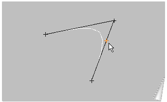
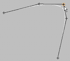
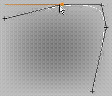
-
Move the cursor over the point you want to align. The
segment closest to the mouse is highlighted. Horizontal and vertical
segments are seen.
-
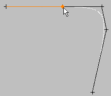
Click the left mouse button. The point close to the
mouse is fixed. The second point moves along the horizontal or vertical
segment.
You can see that the point below the selected point has moved up.
The choice of horizontal or vertical segment is automatic and the chosen
direction depends on the smallest angle of rotation.
|
| |
Adding Weight to the
Points
|
| |
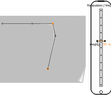
-
Click Attraction
 to add weight to the point. A new icon
is added to Tools Palette. The icon has two states:
to add weight to the point. A new icon
is added to Tools Palette. The icon has two states:
-
 Sharp Attraction: Selecting this gives a
sharp edge.
Sharp Attraction: Selecting this gives a
sharp edge.
-
 Smooth Attraction: Selecting this gives a
smooth edge.
Smooth Attraction: Selecting this gives a
smooth edge.
|
|
|
You can also access this command by
pressing CTRL+SHIFT+F. |
-
Select the point.
A slider indicating the value of the weight is displayed on
the right of the screen and can be changed between 0 and 100.
- Hold the
left mouse button and move the mouse to reach the desired value on the
weight slider. Release the left mouse button when you are satisfied with
the weight added to the surface.
|
| |
Erasing a Point
|
| |
-
Click Erase Point
 to delete a point.
|
|
You can also access this command by
pressing CTRL+SHIFT+E. |
-
Select a point.
The point is deleted.
|
| |
Closing the Curve
|
| |
-
Click Close Curve
 to close the curve. The icon is now changed to
 . .
|
|
You can also access this command by
pressing CTRL+SHIFT+C. |
-
Click Close Curve again to open the curve.
|
| |
Reframing on
Drawing View
|
| |
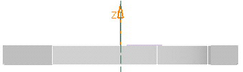
-
Click Drawing view
 reposition the view to drawing view (the plan).
|
|
You can also access this command by
pressing CTRL+SHIFT+R. |
|
| |
Defining
the Extrusion Length
|
| |
-
Click Length
 to position the view laterally such that the length of extrusion can be changed.
The Tools Palette is modified.
|
|
You can also access this command by
pressing CTRL+SHIFT+L. |
-
Hold down the left-mouse button and drag to the
surface to extrude it along the defined direction. You can also use
Extrusion Edition
command to define the extrusion length.
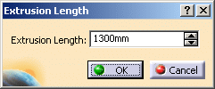
-
Click Extrusion Edition
 . The
Extrusion Length dialog box is displayed. . The
Extrusion Length dialog box is displayed.
-
Enter the length to be extruded or use spinners to change the
value. In this case enter the value as 1300mm.
-
Click OK.
-
To go back to drawing view (plan), click Drawing view
 . .
|
| |
Apply Command
|
| |
-
Click Apply
 to validate and create the extruded surface.
-
The Manipulation
 command along with Tools Palette is automatically activated,
allowing you to manipulate the surface.
command along with Tools Palette is automatically activated,
allowing you to manipulate the surface.
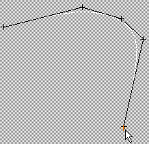
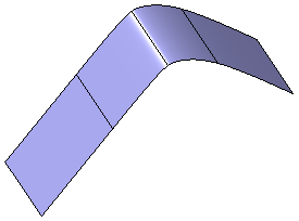
The final surface without any manipulation is as seen:
|
 |
- You cannot use a pre-existing curve for surface creation.
- Undo and Redo commands are not
available.
|
|
 |