 |
This task shows how to mesh a cloud of points or regenerate an existing
mesh.
The Mesh Creation and the Mesh Regeneration actions
offer:
- a neighborhood parameter that makes it possible to fill holes or to
let some areas unmeshed,
- an automatic detection or a manual definition of the meshing plane for
the 2D mesher,
- boundary continuity with contiguous meshes through the
Constrained option,
- a fully automatic 3D meshing (c)INRIA, suitable for
mechanical parts
with blind or through holes, that respects details, especially sharp
edges,
- a sag value to mesh dense clouds with a reduced number of triangles,
but still respecting the 3D Shape within a given tolerance.
|
 |
In STL Rapid Prototyping, Mesh Regeneration is
allowed on meshes only,
i.e. objects whose partially or totally active cells are meshes.If this
is not the case, a fatal error panel is displayed:
Mesh Regeneration is allowed on meshes only. |
 |
Open the
Cloud.CATPart model from the samples directory. |
 |
-
Click Mesh Creation or Mesh Regeneration
 . .
The Mesh Creation dialog box is displayed.
-
Select the Execution Mode
option you need:
- 3D Mesher this is a meshing method for complicated
shapes
(e.g. mechanical objects, clouds that can not be projected onto a
single plane,
or without draft characteristics).
This is the default option.
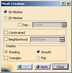
- This mesher provides a Sag option to reduce the
number of triangles computed on dense clouds.
However, this option respects the shape of the object.
- You would achieve the same result by filtering the cloud
with the adaptative option set
to the sag value and meshing the output.
- You can also mesh a cloud with a sag equal to 0. This
means that all the points are meshed.
This algorithm is more suitable to mesh large clouds quickly.
|
|
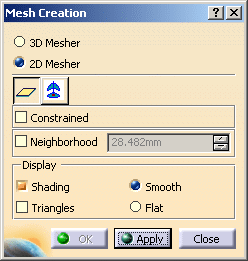
- 2D Mesher: this is a less complex meshing method, to
apply to simple objects, i.e.
that can be projected onto a single plane (smooth shapes).
The entry dialog box is replaced with that of the 2D Mesher.
 |
|
|
| |
-
If you have selected the 3D Mesher, if necessary select
the sag check box and type its value,
or keep the default 3D Mesher.
-
If you have selected the 2D Mesher, select the plane that
is the computation reference for the meshing:
-
either one main plane

-
or one defined with the compass

The quality of the mesh depends on the computation
direction. |
-
A Neighborhood value is proposed in accordance
with the model.
This value represents the maximal edge length of the triangles displayed.
The value proposed is just an approximation of this value.
Its relevance depends on the distribution of the points in the cloud.
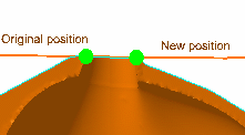
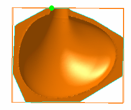
It is visualized by a sphere. You can change its position by a simple
mouse click.
 |
| The sphere is updated when you change the Neighborhood
value. |
 |
-
Select the Display option you need:
- Triangles to display only the mesh,
- Shading to simulate the surface of the object:
- with the Flat option, the light is sent on the
triangles along their normal,
- with the Smooth option, the light is smoothed over
the triangles,
giving a better image of the quality of the surface.
|
|
 |
- Meshing requires a complex computation.
The computation time will increase according to the size and complexity of
your model.
You may want to filter the cloud before starting the meshing.
- To mesh large quantities of points, we recommend the following
settings:
- Sag=0mm
- Triangles not activated
- Shading activated, with the Smooth option.
|
 |
These display options are applied within this action only.
Once you have validated the result with OK, the result is displayed in the
Smooth mode,
even if the input element or the computed mesh were displayed in another
mode. |
| |
-
Constrained is used to:
- re-process a portion of a mesh by adding points to an existing
mesh or
reprocessing a meshed cloud that has been unfiltered:
Open the
Mesh2.CATPart model from the from the Samples directory.
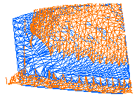
The original mesh had holes in it. Select a faulty portion and
proceed to a new meshing on that portion.
The original mesh is in red. The re-processed mesh is in blue.
 |
|
- connect several meshes:
Open the
Mesh1.CATPart model from the Samples directory. Draw two traps
on that part and mesh
them with different values, as shown below. Now activate the
remaining square of points, as shown below.
|
-
For quicker meshing performances, you can filter portions
of the parts according to your successive needs.
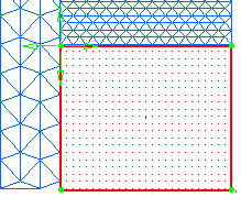
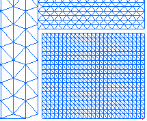
The mesh is unconstrained, the activation trap does not
overlap the previous meshes.
The resulting mesh is independent from the other two. |
  |
 |
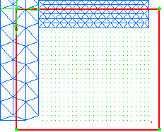
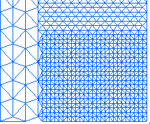
The mesh is constrained, the activation trap overlaps the previous
meshes.
The resulting mesh is connected to the other two.
Facets of the existing mesh that were totally or partially inside the
trap have been removed
and recomputed to adjust to the additional mesh. |
  |
 |
-
Click Apply to check or update the result.
Then click OK to confirm the result and exit the action.
An element Mesh Creation.x is created in the specification
tree.
|
 |
Increase the Neighborhood value to improve the
mesh or reduce it to avoid filling holes that should remain clear:
Triangles:
|
|
Shading:
|
 |
-
They indicate that the normals to the facets have
different directions at this place.
-
In 2D and 3D mode, some triangles
may overlap and mesh should be corrected.
-
In Constrained mode, they show the common
boundaries of meshes.
-
When computing a constrained mesh, type 0 as the
Neighborhood value to check the boundaries of the mesh.
If the boundaries are not satisfactory, modify the mesh plane to improve
them.
-
After the computation of a constrained mesh, two mesh
elements are visible in the specification tree:
the constrained mesh and the initial mesh. You can select one and then the
other to make sure they are complementary.
-
You can use the Meshes
Merge action to obtain a single mesh.
|
|
 |
![]()