This task explains how to apply a sticker on a digital mockup (i.e. CATProducts, CATParts, cgr and MultiCAD files).
Select Tools > Options > General > Display > Navigation then
activate the Highlight faces and edges option. This option enables to
highlight the sticked face.
Click also Shading with Material
![]() in the View toolbar.
in the View toolbar.
-
Click Apply Sticker
 to open the Sticker dialog box:
You can also select directly in the geometry area the element onto which the sticker will be applied then click Apply Sticker. If you do so, you can skip step 2 and jump to step 3. 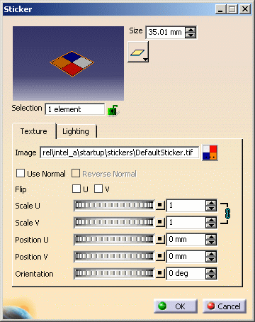
-
Select the 3D geometry location where you want to apply the sticker:
- for a V5 model, you can either select one or multiple elements using the multi-selection in the 3D window or select the desired element(s) in the specification tree
- for a V4 model, you can select a face or the entire product as well either in the 3D window or in the specification tree
- for cgr and MultiCAD files, you can select either a face or the entire product in the 3D window or in the specification tree. As far as cgr files are concerned, the sticker will be applied onto the entire product.
However, note that applying a sticker onto the entire product will result in a longer response time when manipulating geometry.

Depending on the location where you click, the sticker is applied the following way:
-
if you click an object in the specification tree, the sticker's manipulator is centered by default on the selected object and its size is proportional to the size of this object
-
if you click an object in the geometry area, the manipulator is centered by default on the point you clicked and is positioned along the normal to this point.
-
Click the
 button to choose the type of mapping: either Planar,
Spherical or Cylindrical.
button to choose the type of mapping: either Planar,
Spherical or Cylindrical.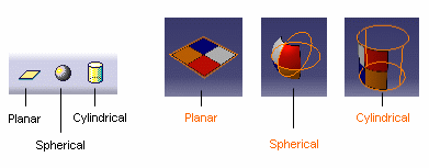
These different mapping types are available to let you select the most appropriate mapping for the shape of the geometry: - Planar Mapping is similar to a slide projector (a picture on a wall, for instance). You can use it for stickers with two privileged directions such as a picture of a chessboard or a wall of bricks
- Spherical Mapping is similar to a painted light bulb. You can use it for stickers that do not have a privileged direction
- Cylindrical Mapping is similar to placing a label on a can of food. You can use it for stickers having a privileged direction such as a picture of marble.
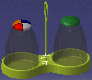
When a sticker is created and applied onto geometry, it is placed under a node named Stickers which is located under the current active product: 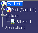
In our example, the symbol identifying the sticker means that the sticker has been applied onto an element and has a texture image. The number of selected elements is displayed in the Selection box.
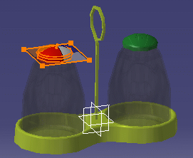
The sticker is applied tangent to the surface with a visualization in transparency and a default image.
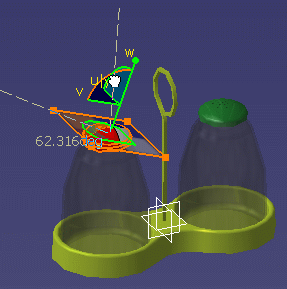
The shape of the manipulator reflects the mapping type selected in step 3 (Planar in our example):
You can assign a new default image to the sticker in the Sticker tab accessible in Tools > Options. -
Use the manipulator handles to adjust the texture scale as shown below:
-
-
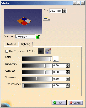
Use the Color slider to set the sticker color or click the ... button opposite Color then choose the color to be used for the material texture. The Color dialog box is displayed allowing you to select the exact color you wish to define as a texture:
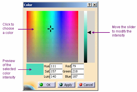
You can click in the preview area to choose the color, or even enter the exact value of the desired color. You can enter a value comprised between 0 and 255 for any of these boxes. When finished, click OK (or Apply then OK) to validate and close the Color dialog box.
-
Define the other lighting parameters:
- Luminosity: determines the intensity of light diffused in any direction by the object, even if not lit by any light source
- Contrast: the intensity of light diffused by the object when lit by light sources
- Shininess: intensity and color of light reflected in one particular direction (highlights)
- Transparency: determines the degree of transparency of an object. The higher the value, the more transparent the object.
-
Click OK to validate your parameters.
The sticker is applied according to the parameter values you specified:
You can create as many stickers as you wish on the same geometry and make them overlap each other, the last sticker created being placed on top.

You are now ready to modify the sticker properties.
![]()