A design table:
|
|
|
|
Screws are a good example of mechanical parts that can be described by a design table. To simplify, imagine they are all described by four parameters: the head width, the head height, the body width and the body height. The sets of four parameter values that can be assigned to a screw can be easily regrouped in a design table. This design table has as many columns as screw parameters and as many rows as sets of parameter values. In a design table, a set of parameter values is called a configuration and it is registered in a row.
The values mentioned in the sheet cells have to be expressed in appropriate units. Otherwise, the right values won't be associated with the document parameters.
|
|
If no unit is mentioned within a cell:
|
|
Here is an example of an Excel sheet:
| column name | column unit | When a configuration which contains empty cells is selected, the parameters associated with the empty cells are not modified. This property enables you to modify parameters but only under certain conditions. | |||
|
|
|||||
| Within a given column, you can change the units. | Units can be specified in cells. No unit = SI |
||||
Note that it is highly recommended to choose the General format and not the Cells format in Excel.
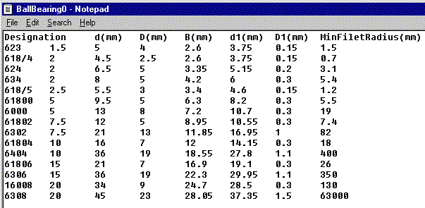
Here is an example of a tabulated file format. You can use your favorite text editor to create this design table. Use the Tab key to skip from one column to the other. Unit rules are the same as for the Excel sheets.

| Under UNIX, it is possible to change the default design
table editor. To do so, type: export CATTextEditorDT=... (indicate the path of the editor.) |
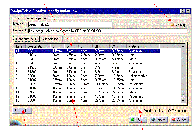
After it has been read and processed by CATIA, the design table looks something like this:
| No units in column | Check box to modify the activity | |
 |
||
| Displays the design table raw data. | Values with units | Duplicates the design table external data into the CATIA document. Check this box whenever you intend to re-access your design table on another platform. |
Design tables can have different statuses:
|
|
Synchronized: The Design Table is copied into the model (Duplicate data in CATIA model checked) and the data stored in the model are synchronized with the content of the file. |
|
|
Not synchronized: The Design Table is copied into the model (Duplicate data in CATIA model checked) and the data stored in the model are synchronized with the content of the file. |
|
|
Inactive: The Design Table is deactivated. The associated parameters are not driven by the design table any longer. |
|
|
Broken: The Design Table is functionally KO because it cannot be used to valuate the associated parameters (data cannot be accessed because the file is lost or there are 2 columns with the same name). |
|
|
Light Broken: The filter is not compatible with the current configuration, or if the current configuration value does not correspond to one of the rows of the file. |
|
When loading CATIA document containing
design table linked to an external file (excel file or tabulated text
file), the system tries to resolve the links to provide access to
these external files. To ensure this, you need to define different link
resolution strategies in Tools > Options > General > Document
tab, Linked Document Localization area. For more information
on this setting, see CATIA Infrastructure's User Guide: Customizing: Document. With no strategy defined or improper strategy, the design table is unable to locate the external file. This results in the following behavior:
|
|
|
|
If you want to be sure that the link will be resolved, activate the option Folder of the link in the Linked Document Localization. |
Design tables cannot handle Excel files containing translated parameters values of Boolean type (for example Falsch instead of False.) When creating your design table in Excel, select Text in the Format Cells window and not General. This way, your values will not be automatically translated.