 |
This task will show you how to generate a ply
book from the manufacturing CPD data structure with the following
functionalities:
- Capability to choose which Composites entities are associated with the sheets
created
(one sheet per Ply or Cut-Piece, one sheet with all
Cut-Pieces or one sheet per sequence).
- For each new added sheet, creation
of all the views corresponding to the reference sheet ones, in terms of
quantity, types and properties.
- For each new created view, the
link to the ply or sequence is replaced by the corresponding ply or sequence for the
ply book.
- Capability to choose and customize the “VB Macro” used for
cartridge generation associated with all sheets.
- Capability to choose
between a generation mode or an update mode.
- Update mode will check entity
names and order between 3D viewer and all the sheets.
You will learn how to:
|
 |
Part_01.CATPart from the samples\Composites directory. You must have
created a Reference Sheet:
-
Start Mechanical Design > Drafting.
In the dialog box that appears, select Empty sheet and click OK.

-
In the Projections toolbar, click Advanced Front View
 . .
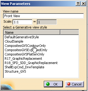
Select a Generative View Style and click OK.
-
In the Composites Design window, holding Ctrl-key down,
select a ply (Ply.1), its reference surface (Extrude.1) and a projection
plane (xz plane).
An oriented view is displayed.
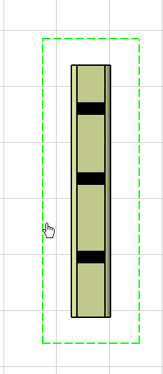
In the Drafting window, drag and drop the frame:
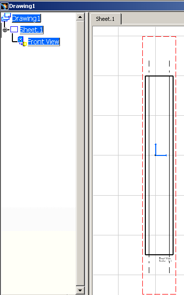
You have created a first front view:
-
If you require shaded plies and need to annotate views,
you need to create a second identical front view:
|
 |
- All the views of the reference sheet must be linked to the same ply or
sequence (and only one entity). However, each view can be linked to other 3D
entities as required.
- Each view can have:
- its own GVS with attributes specific for Composites entities. See
Producing Drawings with Generative View Styles for more
information.
- its own angle and scale.
- If the reference sheets contains several views,
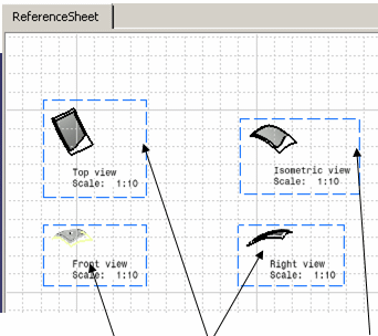 |
| the different views (front, top, right, iso) are created and
positioned as desired on the sheet. |
|
 |
-
In the Drafting workbench, click New
Ply Book
 in the Composites Ply Book toolbar (deep on the right side).
The Ply Book dialog box is displayed:
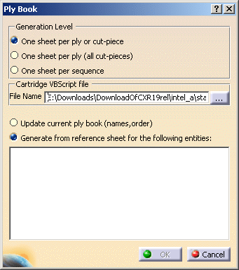
-
Select the
Generation Level
you need

A default
Cartridge VBScript file is proposed. Click ... and browse your
directories to select another file.
|
 |
- You can provide a default path for the template in the
Tools>Options>Mechanical Design>Composites Design tabpage.
- You can modify the cartridge using a VBScript macro. A sample
Drawing_Cartridge_PlyBook.CATScript is
provided under
C:\Program Files\DassaultSystemes\Bxx\intel_a\VBScript\FrameTitleBlock
- You can add specific data to the cartridge in new lines or columns.
- You cannot modify the macro input method signature, i.e. you cannot
avoid Composites Design data generation in the cartridge
- To create a cartridge via a macro or interactively, you must respect
the following naming conventions:
- For the ply: TitleBlock_Text_PlyName
- For the material: TitleBlock_Text_PlyMaterial
- For the direction: TitleBlock_Text_PlyDirection
- For the thickness: TitleBlock_Text_PlyThickness
- For the sequence: TitleBlock_Text_PlySequence
- For the ply group: TitleBlock_Text_PlyGroup
|
|
|
-
In the Composites Design window, select the stacking.
You can select the stacking or a group of plies, sequences or individual plies,
cut-pieces or cores
you want to export.
The dialog box is updated accordingly:
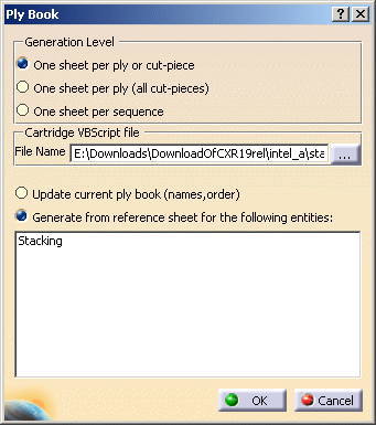
|
 |
If you select One sheet per sequence, you cannot select
individual plies or cores. |
| |
-
With Stacking highlighted in the dialog box, click
OK.
A progress bar is displayed while the sheets are computed.
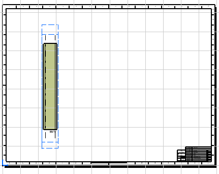
- A new sheet is created per composite entities,
- If you have selected a sequence or a ply pointed by the
reference sheet views, ia new sheet will not be created for it, i.e.
the reference sheet is not duplicated.
- A copy of all the views of the reference sheet is created for
all other plies in new sheets with:
- the same view properties (Type, Angle, Scale),
- the same position in the sheet,
- the same links (except for the link to ply or sequence),
- for each view, the link to the ply or sequence is replaced by
the corresponding ply or sequence for the ply book,
- if you have selected One sheet per sequence, and if a
view of the reference sheet references a ply (or the other way
around), the links in the reference sheet will change and will be
associated with the sequence.
Example of specification tree:

Example of a sheet:
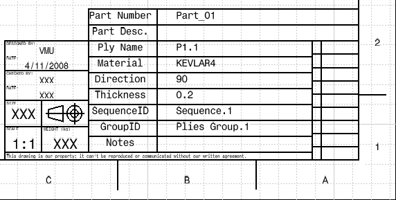
Detail of the cartridge:
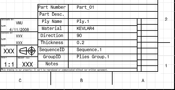
A cartridge is generated in the reference sheet and in all the new
sheets (Background view) through a VBScript file.
It contains:
- Composites Design information (Ply name, Direction, Material,
Thickness, Sequence ID, Group ID),
- Part information (Part Number, Part Description),
- generic information (Date, Designer, Scale …),
- if you create one sheet per ply, and have selected a ply without
geometry but with an OpenBody named Notes (that name is
compulsory) that contains notes (knowledge parameters), those notes
are added in the Notes box of the cartridge. You are also warned
that the raster view for this ply could not be generated.
|
|
 |
- Printing of all the sequence sheets is possible.
- Additional views or sheets must be manually inserted in the drafting
workbench.
|
|
|
An error message will be displayed if:
- you have not selected an entity as input,
- the reference sheet does not contain any view,
- one or several reference views are not linked to Composites Design
entities,
- the Cartridge VBScript file does not exist.
|
|
|
An Update of the Ply Book is required when:
- names of plies or sequences or cut-pieces have changed,
- plies or sequences or cut-pieces have been re-ordered.
-
In the Composites Design part, change names of plies, for
example, change Ply.1 and Ply.2 to P1.1 and P2.2.
-
In the Drafting workbench, click New
Ply Book
 . .
The Ply Book dialog box is displayed:

-
Select Update current ply book (names, order)
and click OK.
New Ply Book:
- scans the existing sheets and check if the sheet names and
cartridge information are exact for each sheet,
- scans the Composites Design part stacking and check if
plies/sequences/cut-piece have been re-ordered compared to the ply
book sheets,
- does not take into account the Generation Level.
When the update is done:
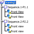
- The name of the sheets corresponding to Ply.1 and Ply.2 have
changed from Sequence.1-Ply.1 to Sequence.1-P1.1 and from
Sequence.2-Ply.2 to Sequence.2-P2.2 (in the specification tree and
on the sheets):
- The corresponding cartridges have changed too:
|
|
|
 |