Fastener Visualization

This page deals with the Fastener Visualization  option for DPM - Fastening Process Planner.
 

Fasteners Assignment

Assignment Status Color

If this option is selected, the color of the fastener on the 3D geometry will reflect the fastener's assignment status when the Fastening Sync command is run.

By default, the option is selected.

Active Validation Rules

Process Syntax Validation

Process syntax validation validates fasteners according to the process.

Collocation Validation


Collocation validation determines whether the fastener's manufacturing and design positions are collocated.

By default, neither rule is selected.

Color Status change flowchart for using the Fastener Assignment, and the Active Validation rules.


Fastener Assignment Status Color

No  Assignment

You can select from a range of colors to visualize the assignment status of the fasteners.

By default, the white shown in the image above is selected for unassigned fasteners.

Invalid  Assignment

You can select from a range of colors to visualize the assignment status of the fasteners.

By default, the red shown in the image above is selected for invalidly assigned fasteners.

Not Validated Assignment

You can select from a range of colors to visualize the assignment status of the fasteners.

By default, the yellow shown in the image above is selected for assigned but unvalidated fasteners.

Valid  Assignment

You can select from a range of colors to visualize the assignment status of the fasteners.

By default, the green shown in the image above is selected for assigned and validated fasteners.

Fasteners in Viewer

Show the design fastener

The design fastener tags can either be visible or hidden.

You can also use this option to determine the color, line type, and weight of the lines that make up the x's marking the design tags.

D By default, the design fastener tags are visible.

Show the line between the design fastener and the manufacturing fastener

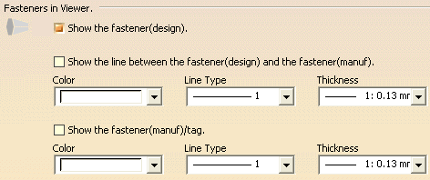
The line between design fastener tags and manufacturing fastener tags can either be visible or hidden. The line can only be visible if both the manufacturing and design fasteners are visible.

You can also use this option to determine the color, line type, and weight of the lines.

The line between the design fastener tags (or positions) and 
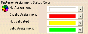
manufacturing fastener tags is unaffected by the assignment status. The status color displayed on the manufacturing fastener tags and the lines that make up the manufacturing fastener tags (tag/frame/coordinate system) are of double thickness while displaying status colors. The orthogonal vectors that make up the manufacturing fastener tags are the ones that are of double thickness.

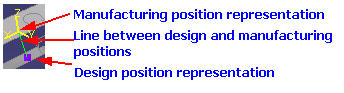
The example below shows the manufacturing tags set as visible, in yellow, and the line between the manufacturing tag and design tag (which is only visible when the two tags are not coincident) set to green.

By default, these lines are hidden.

Show the manufacturing fastener

The manufacturing fastener tags can either be visible or hidden.

You can also use this option to determine the color, line type, and weight of the lines that make up the x's marking the manufacturing tags.

By default, the manufacturing fastener tags are hidden.

CGR from XML

Default path for the XML document

To customize the visualization of a fastener, users can customize an XML file that points to a CGR file.  The location of the XML document is set in this tab.

D The default value for the path is shown.

Default File Name for the XML document

The default XML file name used is listed in the tab.

By default, the name is Weld Text.