3D PLM Enterprise Architecture |
User Interface - Commands |
Managing SelectionRetrieving an existing object from a mouse click |
| Use Case | ||
AbstractThis article shows how to retrieve, in a state dialog command, an existing object from an end user mouse click above this object in a viewer. |
This use case is intended to show how to retrieve, in a state dialog command, an object that exists in a document displayed in a viewer onto which the end user left clicks. This object can be used afterwards as input for any tasks, such as creating a plane from three successive existing point selections in this example. This example shows also how a dialog agent can be reused in several states.
[Top]
The Plane command is a use case of the CAADialogEngine.edu framework that illustrates the DialogEngine framework capabilities.
[Top]
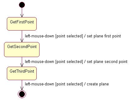
CAADegCreatePlaneCmd is a state dialog command that creates a plane in the 3D space according to the following UML statechart diagram [1].
The dialog is as follows:
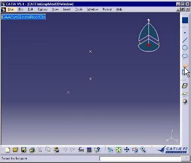 |
Select the plane command. Three points must exist in the document. The active state becomes GetFirstPoint. |
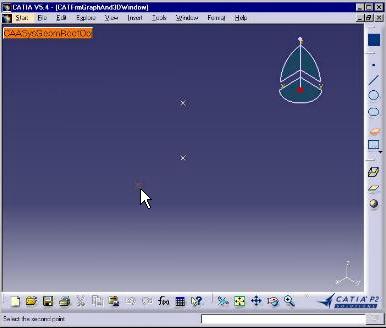 |
The first point is selected. The active state becomes GetSecondPoint. |
 |
The second point is selected. The active state becomes GetThirdPoint. |
 |
The third point is selected. The plane created passes by these three points. The plane symbol is located around the first selected point. The command is complete. |
The CreatePoint command is a straightforward state dialog command with three
sequential states to select the three points defining the plane. The selection
agent [2] is associated with the three point selection
states. It needs to be reinitialized in each transition before the next state
becomes active. To simplify the BuildGraph method, undo/redo [3]
is not taken into into account.
[Top]
See the section entitled "How to Launch the CAAGeometry Use Case" in the "The CAAGeometry Sample" use case for a detailed description of how this use case should be launched.
Then, in the window where you run the mkrun command, do not type the module name on the command line, but type CNEXT instead. When the application is ready, do the following:
[Top]
The Plane command is made of a single class named CAADegCreatePlaneCmd located in the CAADegGeoCommands.m module of the CAADialogEngine.edu framework:
| Windows | InstallRootDirectory\CAADialogEngine.edu\CAADegGeoCommands.m\ |
| Unix | InstallRootDirectory/CAADialogEngine.edu/CAADegGeoCommands.m/ |
where InstallRootDirectory is the directory where the CAA CD-ROM
is installed.
[Top]
To select the second point, there are six steps:
| # | Step | Where |
|---|---|---|
| 1 | Declare the selection agent | Header file |
| 2 | Instantiate the selection agent | BuildGraph method [4] |
| 3 | Assign the selection agent to the GetSecondPoint state | BuildGraph method |
| 4 | Create a transition from the GetSecondPoint state triggered by the selection agent valuation | BuildGraph method |
| 5 | Retrieve the selected point for further plan creation | Transition action method CreatePoint |
| 6 | Release the selection agent | Destructor or Cancel method |
The condition method is not described. It uses the same selected point retrieval code than the action method.
[Top]
The state command class derives from CATStateCommand.
class CAADegCreatePlaneCmd : public CATStateCommand
{
  ...
  private :
    CATPathElementAgent * _daPathElement;
    ...
|
A pointer to the selection agent is declared as a private data member. Selection agents are instances of the CATPathElement class. A single selection agent is enough for the three point selections. It will be recycled after each selection to be used as a brand new one.
[Top]
The selection agent is instantiated in the command BuildGraph
method.
void CAADegCreatePlaneCmd::BuildGraph()
{
  ...
  _daPathElement = new CATPathElementAgent("GetPoint");
  _daPathElement->AddElementType("CAAISysPoint");
  ...
|
The character string GetPoint defined as the argument of the
CATPathElementAgent constructor is the selection agent identifier. This
identifier can be used to assign undo/redo prompts replacing the Undo and Redo
items in the Edit menu. Thanks to the AddElementType method, the
selection agent is valued only when an object that implements the CAAISysPoint
interface is selected. The selection agent remains impassive when any object
that doesn't implement this interface is selected.
[Top]
Still in the BuildGraph method, the GetSecondPoint state is
created, and the selection agent is added to this state. This makes it possible
to value the selection agent when this state becomes the active one.
  ...
  CATDialogState *stSecondState = AddDialogState("stSecondPointId");
  stSecondState->AddDialogAgent(_daPathElement);
  ...
|
The AddDialogState method creates a new dialog state and adds it
to the states managed by the dialog command. The AddDialogAgent
method adds the selection agent to the state.
[Top]
The transition between these two states is created in the BuildGraph
method. This transition is triggered when the selection agent is valued, that is
when the end user clicks an existing point. The guard condition is checked, and
if it returns True, the action is performed.
  ...
  CATDialogTransition *pSecondTransition = AddTransition
  (
    stSecondState,
    stEndState,
    AndCondition(IsOutputSetCondition(_daPathElement),
                 Condition((ConditionMethod) & CAADegCreatePlaneCmd::CheckPoint2)),
    Action((ActionMethod) & CAADegCreatePlaneCmd::CreatePoint,
            NULL, NULL, (void *) 2)
  );
  ...
|
The AddTransition method creates a transition and adds it to the
transitions managed by the dialog command. Pointers to the transition's source
and target states are the first and second arguments respectively. The
transition trigger is defined in the guard condition as the first condition to
be checked using the IsOutputSetCondition method applied to the
selection agent. This condition returns True when the selection agent is valued.
A second condition uses the CheckPoint2 method to check that the
selected point is not identical with the first one. If this was the case, the
plane would be undetermined. Because we use AndCondition to create
the guard condition, both condition methods must return True to fire the
transition. In this case, the CreatePoint(void * 2) action method
is executed. Since the same action method is used for the first and second
point, the point index is passed as argument to help differentiate the two
cases. The two NULL parameters are put in place of the undo and
redo methods.
[Top]
When the end user has clicked to select a point, the transition between the GetSecondPoint and GetThirdPoint states is triggered, and if the guard condition returns True, the following action method executes. It first retrieves the selected object paht element.
...
CATBoolean CAADegCreatePlaneCmd::CreatePoint(void *iPointIndex)
{
  int index = (int ) iPointIndex -1;

  // Gets x,y,z from the selected point
  float x,y,z ;

  CATPathElement * pModelPath = _daPathElement->GetValue();
  CATBaseUnknown * pExpectedPoint = NULL ;
  if ( pModelPath && pModelPath->GetSize() )
  {
    int ElementCountInPath = pModelPath->GetSize() - 1;
    pExpectedPoint = (*pModelPath)[ElementCountInPath];
  }
  ...
|
The selection agent is valued by the end user click. The first thing to do is
to extract this value using the GetValue method. The retrieved path
element instance is a table whose elements contains theobjects of the path from
the root object to the selected object. The selected object is contained in the
last table element.
Now from this selected object, we retrieve a pointer to the CAAISysPoint interface and get the selected point coordinates that we assign to the temporary point stored as a state dialog command class data member.
  ...
  if ( pExpectedPoint )
  {
    CAAISysPoint * pExpectedPointAsISysPoint = NULL;
    HRESULT rc = pExpectedPoint->QueryInterface(IID_CAAISysPoint,
                                                (void**)&pExpectedPointAsISysPoint);
    if (SUCCEEDED(rc))
    {
      pExpectedPointAsISysPoint->GetCoord(x,y,z);
      _Point[indice].SetX(x);
      _Point[indice].SetY(y);
      _Point[indice].SetZ(z);
      pExpectedPointAsISysPoint->Release();
    }
  }
  ...
|
QueryInterface must succeed because the selected object can be
selected if and only if it implements CAAISysPoint. This was stated in 1
when instantiating the dialog agent. Once the temporary point is assigned the
selected point coordinates, the pointer to CAAISysPoint is released.
Before leaving the method, the selection agent is reinitialized. This makes it possible to reuse it in a later step.
... _daPathElement->InitializeAcquisition(); return TRUE; } ... |
[Top]
A pointer to the selection agent was created in the command BuildGraph
method as a data member to be accessed and used in different methods. It
should be released when it becomes useless. This can be done in the command
destructor, as shown here. This could also be done in the Cancel
method called just before the destructor.
CAADegCreatePlaneCmd::~CAADegCreatePlaneCmd()
{
  ...
  if (_daPathElement) _daPathElement->RequestDelayedDestruction();
  _daPathElement = NULL ;
  ...
|
[Top]
This use case shows the objects involved in an end user selection: the state
dialog command, the statechart and its implementation in the BuildGraph
method, the states, the selection dialog agent, the transition along with
its composite condition and action, and the way to retrieve the selected object.
It also shows how to use the same dialog agent in several states.
[Top]
| [1] | Describing State Dialog Commands Using UML |
| [2] | Managing Selection |
| [3] | Managing Undo/Redo |
| [4] | Implementing the Statechart Diagram |
| [Top] | |
| Version: 1 [Jan 2000] | Document created |
| [Top] | |
Copyright © 2000, Dassault Systèmes. All rights reserved.